
Introduction
Crane runway beam design in heavy industrial workshops demands a rigorous integration of load analysis, fatigue-resistant detailing, and environmental protection strategies. Designing crane runway beams requires managing dynamic loads and structural fatigue simultaneously-failure in either domain can lead to catastrophic structural collapse, prolonged operational downtime, and significant safety hazards. For structural engineers and facility managers overseeing overhead cranes in steel mills, chemical plants, and heavy manufacturing facilities, understanding the interplay between heavy loading, chemical degradation, and cumulative fatigue damage is essential.
This article covers the full scope of crane runway beam design for heavy duty cranes, including load path analysis, fatigue evaluation methodology, chemical hazard mitigation, and facility upgrade planning. It addresses compliance with Singapore’s statutory requirements under BCA and MOM frameworks while referencing international standards from CMAA and Eurocode 3. Light industrial or residential crane applications fall outside this scope.
The target audience includes facility managers, structural engineers, and industrial maintenance teams responsible for crane systems in manufacturing and heavy processing environments-professionals who must balance operational demands with structural integrity and regulatory compliance.
Effective crane runway beam design requires comprehensive load calculations, fatigue-resistant connection details, and proactive maintenance strategies to handle heavy industrial loading while preventing premature structural failure. Runway beams must support vertical and lateral loads across millions of loading cycles, and each design decision-from weld geometry to material grade-directly influences the fatigue life of the entire runway system.
Key outcomes from this article:
-
Proper load calculations for heavy cranes including dynamic amplification and horizontal forces
-
Fatigue design principles with critical detail identification and stress range analysis
-
Chemical hazard mitigation strategies for corrosive workshop environments
-
Compliance pathways for Singapore statutory requirements under BCA and MOM
-
Maintenance scheduling strategies integrating non-destructive testing and alignment monitoring
Understanding Crane Runway Beam Systems in Industrial Environments
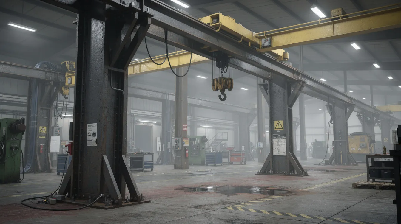
A crane runway beam (also called a runway girder or crane girder) is a stationary steel member that supports the overhead crane’s wheel loads and transmits them into the building structure-columns, foundations, and lateral bracing systems. These structural components form the backbone of any bridge crane installation, carrying the full weight of the crane bridge, trolley weight, and lifted load while accommodating the dynamic effects of crane operation. Steel is the standard material for runway beams due to its high strength-to-weight ratio and predictable fatigue behavior.
The load transfer mechanism follows a clear path: crane wheel load acts on the crane rails, which transfer forces through rail attachments (welded or bolted) into the runway beam’s top flange. Bending stresses develop through the web to the bottom flange, and the loads ultimately pass through supporting structure connections to columns and down to foundations. This load path must accommodate vertical and lateral forces, longitudinal forces from braking, and torsional effects from eccentric loading-all simultaneously.
Heavy Industrial Loading Characteristics
Heavy industrial crane systems generate complex, multi-directional loading patterns that drive both ultimate limit state and fatigue design. Vertical loads include crane dead load (the weight of the crane and hoist), the payload or lifted load, and trolley weight. A 50-ton crane generates dynamic loads requiring precise structural geometry to distribute forces evenly across beam flanges and connections. Vertical loads must be increased by impact factors to account for dynamic conditions-impact factors typically add 10-25% to crane load calculations, though heavy duty cranes with aggressive duty cycles may see dynamic loads that can double static wheel loads on girders.
Lateral loads arise from crane acceleration, deceleration, and skewing. Transverse forces occur when the trolley skews during crane movement, generating horizontal forces that the runway beam must resist. Longitudinal forces from braking act in the longitudinal direction and require dedicated longitudinal bracing systems. Recent research (2026) demonstrates that neglecting horizontal crane actions in fatigue assessments-acceleration, deceleration, skewing-substantially underestimates fatigue utilization in welded web-flange connections. CMAA specifications guide design and impact factors for cranes, and crane classifications determine loading frequency and fatigue cycles; for example, CMAA Class C cranes require fatigue considerations in design due to their moderate service frequency.
The connection between heavy loading patterns and fatigue development is direct: crane runway beams experience thousands of load cycles daily. Each passage of the crane bridge generates stress cycles in the runway girder, and the cumulative effect of repeated loading-not just maximum wheel loads-drives fatigue damage accumulation. Fatigue is caused by fluctuating stress ranges and not just maximum loads, making the operational load spectrum a critical design input.
Chemical Hazard Considerations
Industrial workshops handling acids, alkalis, salts, or chemical vapors present severe environmental challenges for crane runway beams. Material degradation from chemical exposure includes corrosion, which reduces cross-sectional area and creates surface pits that act as stress concentrations. These pits effectively widen the stress range (Δσ) at critical locations, dramatically reducing fatigue life. In weld heat-affected zones, hydrogen ingress from chemical environments can cause embrittlement, making crack initiation far more likely under cyclic loading. Corrosion protection is vital to prevent fatigue crack initiation in beams operating in such environments.
Protective coating systems must be specified to withstand the specific chemical environment. Epoxy and polyurethane systems certified to ISO 12944 provide baseline protection, while galvanization or weathering steels offer alternatives in moderately aggressive conditions. For highly corrosive environments, stainless steel rail components or sacrificial coating systems may be necessary-with careful attention to compatibility of weld consumables to prevent galvanic corrosion at dissimilar metal interfaces.
The relationship between chemical exposure and accelerated fatigue crack propagation is synergistic: corrosion creates initiation sites, and cyclic stress drives crack growth from those sites at rates far exceeding what either mechanism alone would produce. This combination demands both enhanced material protection and more conservative fatigue design assumptions.
Statutory Requirements in Singapore
Singapore’s Building and Construction Authority (BCA) mandates that crane loads in structural design must comply with SS EN 1991-3:2010 + C1 (2023) for actions induced by cranes and machinery. The BCA Approved Document (V7.08) specifies that any works involving foundation and supporting frames for overhead cranes, jib cranes, or monorail hoists that are independently supported require structural plan submission by a Qualified Person (QP). Fatigue assessment follows SS EN 1993-1-9:2010 with the Singapore National Annex, which provides locally determined values for fatigue parameters. Runway beams must meet local building codes for safety compliance, and different regions adopt varying standards for crane runway beam design.
The Ministry of Manpower (MOM) enforces the Workplace Safety and Health (Operation of Cranes) Regulations 2011, which require safe installation, periodic inspection, certified operators, and approved crane contractors. OSHA requires initial inspections before crane use, and frequent inspections are required for crane systems under workplace safety frameworks. While MOM regulations focus on operational safety rather than explicitly addressing structural fatigue, they mandate structural adequacy and safe working loads-obligations that inherently depend on proper fatigue design and ongoing structural inspection programs.
Additionally, structural steel fabricators in Singapore must hold FPC (Factory Production Control) certification under SS EN 1090-1 & 2, ensuring weld quality, material traceability, and execution standards that directly influence fatigue performance. This regulatory framework connects compliance to design methodology and fatigue management strategies-every design decision must be traceable through fabrication to installation.
Design Principles for Heavy Industrial Loading
With the loading environment, chemical hazards, and regulatory framework established, the design phase must translate these requirements into specific beam sections, connections, and material specifications that deliver adequate structural stability across the full design life. Runway beam design for heavy duty cranes involves balancing strength against stiffness, fatigue resistance against cost, and constructability against ideal structural geometry.
Load Path Analysis and Beam Sizing
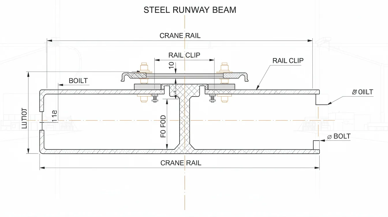
Comprehensive load combination analysis must account for crane loads (vertical, lateral, and longitudinal), building loads (dead, live, wind, seismic), and environmental factors including thermal expansion. Runway beams must support vertical loads from cranes while simultaneously resisting horizontal forces during crane operation. CMAA and FEM provide guidelines on deflection limits for cranes, and load calculations must incorporate all dynamic amplification factors specified in SS EN 1991-3.
Beam section selection targets high moment of inertia for stiffness and adequate depth to keep bending stresses low for a given curvature. However, fatigue design introduces constraints: excessively thick web sections can exhibit lower fatigue strength at welds due to size effects, and deeper sections may increase local stress at wheel load introduction points. Simple span beams avoid complex fatigue issues at column connections, making them the preferred configuration for fatigue-sensitive applications. The selection process must balance strength, stiffness, and fatigue resistance-optimizing for one parameter alone invariably compromises another.
Connection design for heavy crane loads requires particular attention to how vertical force and lateral forces transfer through bolted or welded interfaces. Use bolted connections over welded connections in high-fatigue areas wherever practical, as welded connections are susceptible to fatigue-driven cracking. Where welding is unavoidable, avoid welding on the tension flanges of crane runway beams, and use continuous fillet welds to prevent stress concentrations in welded joints. Connections must also accommodate thermal expansion and contraction-runway beams should allow for thermal expansion through sliding bearings or slotted bolt holes at appropriate intervals.
Deflection Control for Heavy Cranes
Strict deflection limits are enforced for crane runway beams to prevent excessive wear on crane wheels, rails, and structural connections. Deflection limits for runway beams are typically L/600 to L/800 for vertical deflection under service loads, with some heavy-duty applications demanding L/800 to L/1000. Lateral deflection restrictions-typically L/400 or stricter-ensure that crane rails maintain accurate alignment and prevent side loads on crane wheels.
Camber requirements offset dead load deflection and maintain rail alignment under operating conditions. Pre-crowned steel beams are fabricated with an upward curvature calibrated so that under full dead load, the beam elevation approaches level. This ensures that under maximum wheel loads, the deflection remains within acceptable limits and the rail alignment stays within tolerance control limits.
The impact of excessive deflection extends well beyond structural concerns. Excessive vibration and excessive deflection cause uneven wheel loading, accelerate rail wear, degrade rail joints, and-critically-increase fatigue stresses at connections by introducing secondary bending and torsional effects. Misalignment can lead to premature component failure across the entire crane system. Maintaining excellent runway alignment prevents additional lateral wheel forces and impact loading that would otherwise compound fatigue damage.
Material Selection for Industrial Environments
High-strength steel grades provide the foundation for heavy-duty crane runway beams. EN 10025 grades commonly specified include S355J2+N for standard heavy-duty applications and S460 for situations requiring higher strength within reduced section depths. Higher yield strength enables smaller, lighter sections, but fatigue strength of welded details is largely independent of base material strength-a fact that frequently surprises designers accustomed to static design optimization.
For chemically aggressive environments, material selection extends beyond the base steel beams. Stainless steel for crane rails and critical fasteners, weathering steel where mild atmospheric corrosion is the primary concern, and specialized weld consumables that resist hydrogen cracking all form part of a comprehensive material strategy. Post-weld heat treatment may be specified where embrittlement risk from chemical exposure or residual stresses is significant.
Material requirements must balance strength, durability, and cost-effectiveness. Specifying S460 throughout an entire runway system rarely makes economic sense when S355 provides adequate strength for most beam positions-strategic use of higher grades at critical locations (support regions, heavily loaded spans) offers better value. The material selection framework feeds directly into fatigue management strategies, as each grade and weld consumable combination carries different fatigue detail categories.
Managing Structural Fatigue in Workshop Environments
Fatigue management moves beyond design principles into the operational reality of workshop environments where crane runway girders accumulate millions of stress cycles over their service lives. Proper detailing in crane runway beams can significantly influence fatigue life, and the assessment methodology must capture the full complexity of actual loading conditions. Advanced finite element analysis plays an increasingly important role in evaluating fatigue-critical details that simplified hand calculations cannot adequately capture.
Fatigue Assessment Procedures
Fatigue evaluation is required when the expected number of significant load cycles exceeds code-defined thresholds-SS EN 1993-6 provisions, adapted through the Singapore National Annex, set minimum cycle counts above which formal fatigue assessment becomes mandatory. Fatigue assessments should consider actual load spectrum and operational patterns rather than relying solely on simplified code provisions.
-
Determine design life and loading cycles: Define the design life (typically 20–50 years) and estimate total wheel passes, hoist operations, and trolley traversals. Monitor the operational history of crane systems to improve fatigue management-recorded data on actual crane usage provides far more accurate cycle counts than theoretical estimates based on crane manufacturer specifications alone.
-
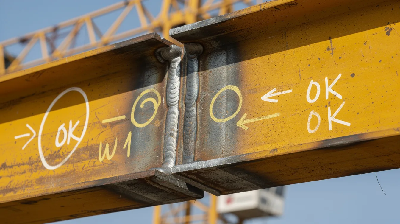
Identify critical fatigue details: Catalog all fatigue-prone details in the runway beam connections and welds-upper flange web-to-flange welds, rail welds (continuous double fillet), end copes, connection weld roots, bolt holes, and any location where structural geometry changes abruptly. Fatigue cracks often initiate at geometric discontinuities or weld details, making this inventory essential. Optimizing FEM analysis for complex steel connections can reveal local stress conditions that inspection alone cannot identify.
-
Calculate stress ranges and apply fatigue categories: Derive the range of stress fluctuation (Δσ) at each critical detail using finite element analysis or simplified beam methods. Include global bending moments, local stress from wheel load introduction, and combined stress components (normal + shear). Recent experimental work demonstrates that traditional detail categories in EN 1993-1-9 do not adequately address nonproportional (multiaxial) fatigue stressing in rail welds and flange-to-web connections, and new test-based categories provide more accurate fatigue strength estimation.
-
Verify fatigue resistance using code provisions: Apply SS EN 1993-1-9 provisions using the appropriate detail category, damage equivalent stress levels, and S-N curves. For facilities designed to AISC standards, AISC 360 provides parallel fatigue provisions. Stress concentrations should be minimized to improve the fatigue performance of crane beams, and the verification must confirm that cumulative damage (Miner’s rule) remains below unity across the full design life.
Critical Fatigue Locations Analysis
The following table compares fatigue-prone locations commonly found in crane runway beam systems, their stress characteristics, and proven design solutions:
|
Fatigue Location |
Typical Stress Behavior |
Common Root Causes |
Design / Mitigation Approaches |
|---|---|---|---|
|
Flange-to-web weld (upper) |
Combined bending + shear stresses; frequent stress reversal; high local stress at weld toe/root |
Partial penetration welds, abrupt geometry transitions, welding defects, high dynamic factors |
Full penetration welds; smooth weld toe transitions; web stiffeners at concentrated load points; apply test-based detail categories |
|
Rail-to-flange welds |
Local load introduction with multiaxial stress; cyclic loading from every wheel pass |
Over-rigid continuous welds prone to root failure; variation in wheel spacing and loading history |
Bolted rail clips where feasible; weld geometry optimization; welded rail splices must be ground smooth to prevent hammering effects |
|
End coping of beams |
Stress concentration at cope corners; principal stress ranges amplified at geometric discontinuity |
Sharp internal corners, small cope radius, frequent load cycling at supports |
Increase cope radius; reduce cope depth; empirical fatigue limit of ~103 MPa at 2 million cycles for end-coped sections |
|
Column connections |
Moment transfer introducing high stress range at weld roots; potential for lateral torsional buckling |
Continuous beam configurations creating negative moments; inadequate stiffening |
Simple span configurations preferred; bolted end plates; adequate lateral stiffness at supports |
|
Block rail joints |
Impact loading at rail discontinuities; hammering effect amplifying dynamic wheel loads |
Misaligned rail joints; inadequate rail joint preparation; thermal gaps |
Precise rail installation with ground-smooth joints; maintain accurate alignment; monitor rail wear patterns |
This analysis helps engineers prioritize fatigue mitigation strategies based on risk-flange-to-web welds and rail connections typically govern fatigue design in heavy industrial applications, while end copes and column connections become critical when beam positions or supporting structure configurations constrain detailing options. Regular non-destructive testing is crucial for detecting fatigue issues in crane systems, particularly at these high-priority locations. Routine inspections should include both visual checks and detailed technical evaluations.
Facility Upgrade Considerations
When industrial facilities upgrade to heavier cranes, existing runway beams often prove inadequate under modern fatigue classification standards. Older designs may have relied on less stringent detail categories or simplified vertical-load-only assessments that substantially underestimate fatigue damage. Assessment methodology for existing beams must include a comprehensive fatigue evaluation against current code provisions, accounting for cumulative damage already sustained during prior service.
Reinforcement strategies include adding cover plates to beam flanges and webs, installing additional web stiffeners, replacing connection welds with bolted alternatives, increasing lateral stiffness through bracing upgrades, and strengthening foundations where column base moments increase. Structural repair and strengthening approaches must be evaluated for fatigue compatibility-repair welds on fatigue-damaged members introduce their own stress concentrations and may not restore original fatigue life.
Cost-benefit analysis must weigh the higher upfront cost of full replacement against the ongoing maintenance burden, downtime risk, and safety implications of reinforcing fatigue-damaged members. In a documented case at a non-ferrous metals plant in Europe, runway beams had been systematically overloaded for decades, producing cracked welds at flange junctions; while reinforcement was technically feasible, cumulative fatigue damage made full replacement the more practical and economical long-term solution.
Common Challenges and Solutions
Heavy industrial crane runway systems face recurring challenges that extend beyond initial design into decades of operational service. Recognizing these patterns early enables proactive intervention rather than reactive emergency repairs.
Premature Fatigue Cracking
Fatigue-prone details include connections and welds in girders, and premature fatigue cracking typically stems from three root causes: poor weld details (undercut, slag inclusions, lack of full penetration), excessive dynamic loading from operational abuse or crane malfunction, and inadequate design verification using simplified fatigue classes when the crane actually experiences high-frequency, heavy loading cycles. Runway girders experience stress cycles from every crane passage, and even minor detailing deficiencies compound across millions of cycles.
Actionable solutions include upgrading weld details to higher fatigue categories, specifying stress relief treatments at critical connections, implementing load monitoring systems that track actual crane wheel load histories, and ensuring beams are installed straight and level to prevent lateral thrusts that lead to fatigue. Daily checks including visual inspections of crane runway systems catch early signs of distress-paint cracking, rust staining at weld toes, or visible deformation-before structural damage progresses. Periodic inspections help ensure crane runway beam alignment, and annual alignment surveys catch drift early to prevent wear.
Chemical Degradation and Corrosion
Environmental assessment must characterize the specific chemical exposure-acidic vapors, chloride-laden atmospheres, alkaline splash zones-and map degradation patterns across the runway system. Areas near process equipment or ventilation intakes typically experience the most aggressive conditions, while beam positions at higher beam elevation may encounter less direct exposure but more condensation-related corrosion.
A comprehensive protection strategy layers multiple defenses: primary barrier coatings (epoxy primers, polyurethane topcoats) certified to ISO 12944 for the specific corrosivity category; cathodic protection for embedded or inaccessible steel beams; material upgrades (stainless steel crane rails, weathering steel for exposed sections); and a scheduled recoating program tied to periodic structural inspection cycles. Engineers monitor rail wear patterns during routine maintenance checks, and corrosion-related section loss must be tracked quantitatively against fatigue allowables. Regular maintenance prevents costly repairs and operational downtime.
Compliance with Evolving Statutory Requirements
Singapore’s adoption of Eurocodes is actively evolving-the transition to Second Generation Eurocodes such as SS EN 1993-1-1:2022 introduces updated provisions that may change fatigue detail categories, partial safety factors, and design verification procedures. Existing crane installations designed to earlier standards may not automatically comply with updated requirements, creating a compliance gap that must be addressed during facility assessments or when modifications trigger structural plan resubmission.
A strategic approach involves phased upgrades prioritized by risk assessment, engaging Qualified Person (QP) engineers for compliance verification, and maintaining comprehensive documentation of both the crane system’s structural design basis and its operational history. Spatial constraints in existing industrial buildings-limited height under rails, fixed column spacing, constrained beam elevation-often prevent adopting ideal section sizes, requiring engineers to explore hybrid solutions, alternate structural geometry, or innovative connection configurations that satisfy both the crane manufacturer’s requirements and the structural code’s fatigue provisions.
Proactive fatigue management and regulatory compliance deliver compounding benefits: reduced unplanned downtime, extended structural service life, lower insurance costs, and-most critically-safe crane operation for personnel working beneath heavy loads every day.
Conclusion and Next Steps
Crane runway beam design for heavy industrial workshops is fundamentally a fatigue design problem. While static strength must be adequate, it is the cumulative effect of millions of stress cycles-amplified by dynamic factors, chemical degradation, and the inevitable imperfections of real-world fabrication and installation-that governs the structural integrity and service life of the entire runway system. Every decision, from beam section selection and weld detailing to material specification and rail installation, directly influences whether a crane runway will perform reliably for decades or develop premature fatigue cracking within years.
Immediate actionable steps for facility owners and engineering teams:
-
Conduct a comprehensive structural assessment of existing crane runway beams, including fatigue evaluation against current SS EN 1993-1-9 provisions with the Singapore National Annex, covering all critical weld details and connections
-
Develop maintenance protocols integrating daily visual inspections, quarterly alignment checks, and annual non-destructive testing programs focused on identified fatigue-critical locations
-
Engage qualified structural engineers for compliance verification against current BCA and MOM requirements, particularly when planning crane upgrades or modifications to existing runway systems
-
Document operational history including actual crane usage patterns, payload records, and incident reports to support more accurate fatigue life predictions
Related topics worth exploring include foundation settlement assessment for heavy crane-supporting structures, building modification design for facility upgrades, and long-term structural health monitoring strategies using AI and sensor-based systems that can track fatigue-relevant parameters in real time.
Additional Resources
-
Singapore BCA Approved Document V7.08: Specifies crane load requirements under SS EN 1991-3 and structural steel design under SS EN 1993 for all structural plan submissions involving crane-supporting structures
-
AISC Design Guide 7: Industrial Buildings-provides comprehensive guidance on crane runway beam design specifications, deflection criteria, and fatigue detailing for North American practice; useful as a comparative reference alongside Eurocode-based design
-
CMAA Specifications (Crane Manufacturers Association of America): Define crane classifications, loading frequency categories, and impact factors that directly feed into runway beam fatigue design
-
Professional engineering consultation: For facility assessments, statutory submissions, and fatigue life evaluations, engaging a qualified structural engineering practice with experience in industrial crane structures ensures both technical adequacy and regulatory compliance