
The main types of pile load testing methods are static load testing, high-strain dynamic testing (Pile Driving Analyzer/PDA), low-strain pile integrity testing (PIT), crosshole sonic logging (CSL), thermal integrity profiling (TIP), bi-directional (Osterberg Cell) testing, and lateral load testing. The selection rule is straightforward: use static testing when you need definitive capacity and settlement verification, PDA when you need rapid capacity estimates and driving stress monitoring, integrity NDTs when you need to confirm structural continuity and detect defects, bi-directional testing when surface reaction systems are impractical for deep bored piles, and lateral testing when lateral resistance governs design.
Catching defects or insufficient capacity early through proactive pile testing reduces the far larger costs of remedial work or structural failure later in a project. For project-specific guidance on combining these methods, the decision framework in the “How to choose which test to run” section below provides a structured checklist.
- Static load test (ASTM D1143): Compression, tension/uplift; definitive capacity and load-settlement behavior.
- Dynamic high-strain test/PDA (ASTM D4945): Rapid capacity estimates, driving stress monitoring, production pile acceptance.
- Low-strain pile integrity test/PIT (ASTM D5882): Non-destructive continuity and defect screening.
- CSL / TIP: Cast-in-place concrete quality, cold joints, and uniformity verification.
- Bi-directional/Osterberg Cell: Deep bored piles where large surface reaction is impractical.
- Lateral load test: Lateral capacity and p-y curve derivation when lateral loading governs.
Table of Contents
- What are the main types of pile load testing methods?
- How does dynamic high-strain testing (PDA) work, and when should you use it?
- What do pile integrity tests and NDT methods detect?
- When is lateral load testing required, and how is it conducted?
- How to plan, instrument, and execute a pile load test safely
- How to choose which pile test to run for your project
- How to interpret pile test results and avoid common pitfalls
- What standards and guidance govern pile load testing practice in the U.S.?
- Key Takeaways
- The case for combining methods, not defaulting to one
- Aectechnicalsg provides end-to-end pile testing oversight for project teams
- Selected standards and guidance for pile load testing
What are the main types of pile load testing methods?
Static load testing is the most accurate direct method to determine ultimate geotechnical pile capacity, performed under ASTM D1143 using hydraulic jacks and a reaction system to measure load-settlement behavior directly. It is the reference standard against which all other methods are calibrated.
Static load test variants
Three loading procedures are recognized for static axial compression tests:
- Quick Load Test (Procedure A, ASTM D1143): Load applied in rapid increments (typically every 2.5 minutes) until failure or a specified terminal condition. Best suited for production pile acceptance when time is constrained.
- Incremental Static Load Test (Maintained Load / ML): Load held at each increment until settlement rate drops below a defined threshold. Preferred for proof testing and when load-distribution data from strain gauges is required.
- Constant Rate of Penetration (CRP): Pile head penetrated at a constant rate while load is recorded. Less common in U.S. practice but useful for research-grade ultimate capacity determination.
Tension/uplift testing follows the same general framework under ASTM D3689, measuring the pile’s resistance to tensile forces, which governs design for structures subject to buoyancy, wind uplift, or seismic overturning.
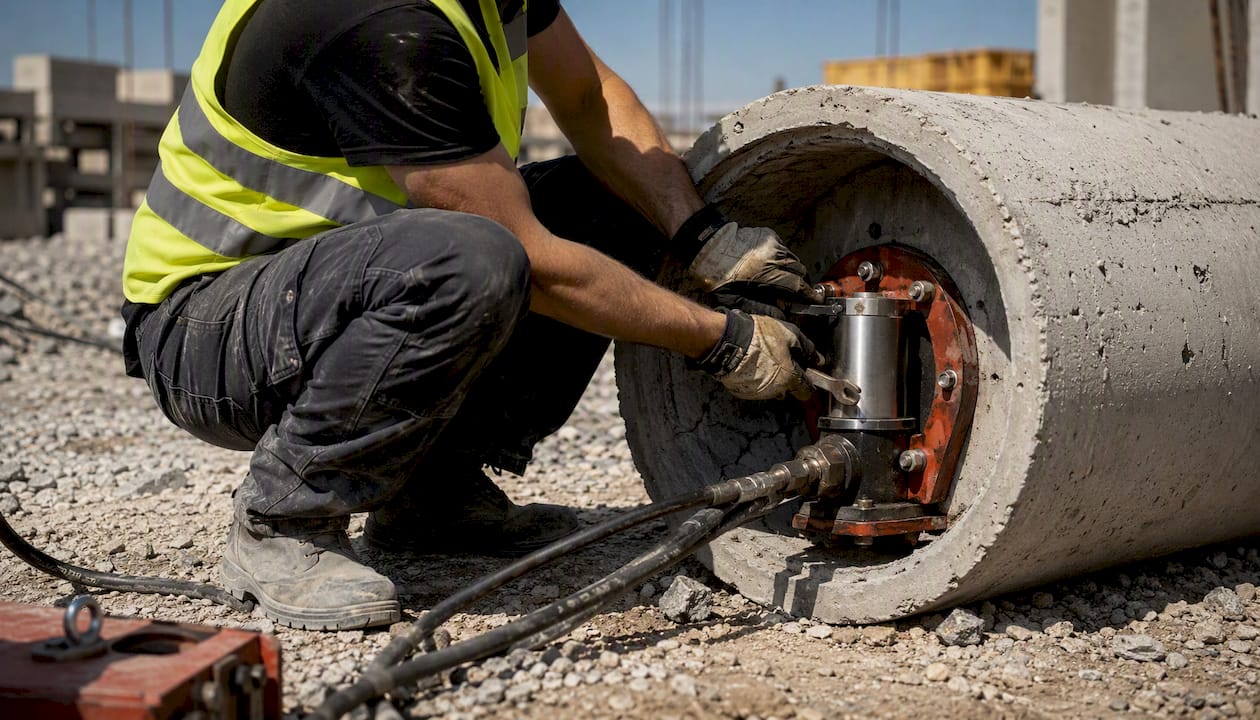
Bi-directional (Osterberg Cell) testing applies load from within the pile using an embedded hydraulic jack, eliminating the need for a large surface reaction frame. The jack combines upward and downward forces to derive an equivalent applied load. However, because load is never applied at the pile top in service conditions, the upper pile segment’s structural adequacy remains unverified and requires supplemental integrity evaluation.
Instrumentation and data quality
A static test produces load-settlement curves as its primary output. Instrumented piles add strain gauges and telltales at depth, which reveal load distribution between shaft friction and end bearing. Combining load cell readings with strain gauge records requires careful attention to hold times. Fellenius guidance recommends holding each load increment for a sufficiently long time, often recommended to be at least 10 minutes or more where feasible for instrumented piles, because strain gauges at depth need time to stabilize. Five-minute holds frequently produce mismatched load-strain records that compromise data quality.
Pro Tip: When specifying an instrumented static test, write the minimum hold time explicitly into the test specification, not just the loading protocol. Vendors who default to 5-minute holds on instrumented piles will produce records that cannot be reliably combined.
| Factor | Advantage | Limitation |
|---|---|---|
| Accuracy | Direct measurement of load-settlement; highest confidence | Requires reaction frame or anchor piles; significant setup cost |
| Soil applicability | Definitive in all soil types | Time-consuming; not practical for every production pile |
| Data richness | Load distribution with strain gauges | Instrumented tests require longer hold times and careful planning |
| Cost/time | Highest confidence for critical piles | Highest cost and longest duration of all methods |
Static tests are essential for cast-in-drilled-hole (CIDH) piles in unproven or variable ground, for critical structures where conservative design assumptions carry significant cost, and as the calibration baseline when PDA is used for production pile acceptance.
How does dynamic high-strain testing (PDA) work, and when should you use it?
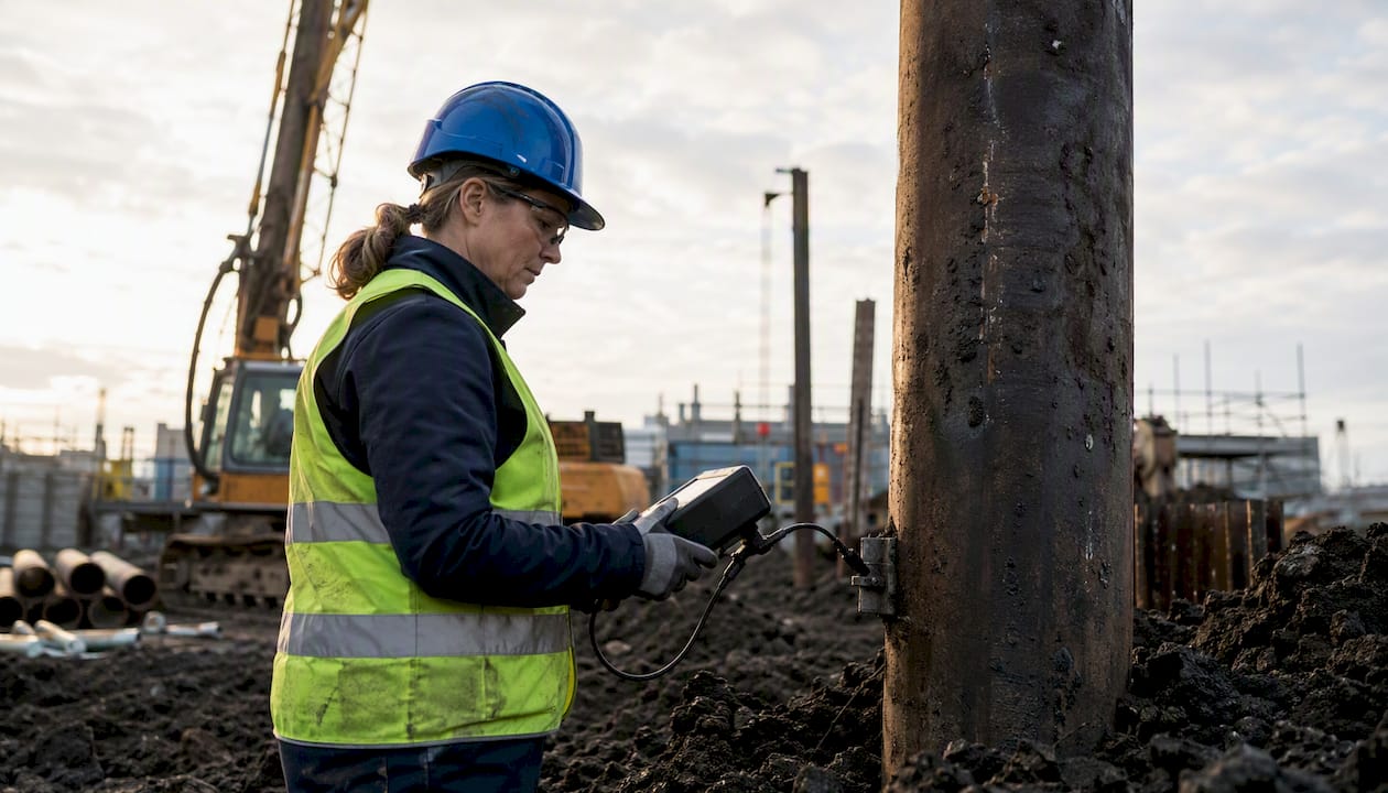
High-strain dynamic testing using a Pile Driving Analyzer follows ASTM D4945 and measures force and velocity at the pile head during hammer impact. Two strain transducers and two accelerometers are bolted near the pile head; the PDA unit integrates the acceleration signal to produce velocity and combines it with force to generate blow-by-blow estimates of capacity, driving stresses, and hammer energy transfer.
CAPWAP signal matching
Raw PDA output provides immediate field estimates, but the definitive capacity evaluation comes from CAPWAP (Case Pile Wave Analysis Program) signal matching performed after the test. CAPWAP iterates a soil model until the computed force-velocity response matches the measured record, producing a static-equivalent resistance distribution that separates shaft friction from end bearing. CAPWAP has demonstrated good correlation with static load tests and is considered state-of-practice for dynamic test interpretation. Most project specifications that accept PDA for production pile acceptance require CAPWAP analysis as the final deliverable, not just the field PDA printout.
Low-strain dynamic screening vs. high-strain capacity evaluation
These are distinct operations. High-strain PDA applies a full hammer blow to mobilize soil resistance and estimate capacity. Low-strain screening (discussed in the next section) uses a light hand-held hammer to generate a stress wave for continuity and defect detection only; it does not mobilize soil resistance and cannot estimate capacity.
Pro Tip: PDA is most reliable in granular soils where soil resistance mobilizes cleanly under impact. In soft clays and silts, set-up effects and rate-dependent resistance can distort capacity estimates; in those conditions, a confirmatory static test is advisable before final design acceptance.
- Instrumentation: Two strain transducers, two accelerometers, PDA data acquisition unit, calibrated hammer with known drop height or energy.
- Data produced: Force-time history, velocity-time history, blow-by-blow capacity estimates, driving stress (compression and tension), energy transfer ratio (ETR), and CAPWAP resistance distribution.
- Advantages: Fast (minutes per pile), cost-efficient for production pile programs, monitors driving stresses to prevent pile damage, applicable during initial drive and restrike.
- Limitations: Less reliable in fine-grained soils without restrike; requires CAPWAP for rigorous acceptance; hammer efficiency must be verified; on-site interpretation is preliminary only.
Dynamic testing is the standard tool for production pile acceptance programs on large projects, where testing every pile statically is cost-prohibitive. Caltrans and state DOT practice consistently recommend pairing at least one static test with PDA analysis to calibrate the dynamic results before relying on PDA alone for production acceptance.
What do pile integrity tests and NDT methods detect?
Low-strain pile integrity testing (PIT), standardized under ASTM D5882, uses a hand-held hammer to introduce a low-energy stress wave at the pile head. An accelerometer records the reflected wave; anomalies in the reflection pattern indicate changes in cross-section, material stiffness, or continuity. PIT detects cracks, voids, necking, and inclusions, but its resolution decreases with depth, and it cannot reliably distinguish between a minor crack and a significant void in deep piles.
Crosshole sonic logging (CSL)
CSL is performed on cast-in-place concrete piles by lowering a transmitter and receiver probe through pre-installed access tubes (typically steel or PVC, cast into the concrete). Ultrasonic pulses travel between tubes; delays or signal attenuation indicate anomalies in the concrete between the tubes. CSL is more sensitive than PIT for detecting defects in large-diameter drilled shafts, but it requires access tubes to be installed before concreting, and it only interrogates the concrete between tube pairs, leaving zones outside the tube grid unsampled.
Thermal integrity profiling (TIP)
TIP measures the heat generated by cement hydration as the concrete cures. A thermal probe lowered through access tubes (or a thermal wire cast into the pile) records temperature profiles; low-temperature zones indicate areas of reduced concrete volume, contamination, or cold joints. TIP is particularly effective for identifying uniformity issues and cold joints in large-diameter CIDH piles and is often run concurrently with CSL to provide complementary data.
When to use each NDT method:
- PIT (ASTM D5882): Early QC screening for driven piles and smaller-diameter bored piles; rapid, low-cost, no access tubes required; best for piles where length-to-diameter ratio is below approximately 30.
- CSL: Large-diameter drilled shafts and CIDH piles where concrete quality is critical; requires access tubes pre-installed; provides zone-specific defect location.
- TIP: Uniformity and cold joint detection in large-diameter cast-in-place piles; can be run through the same access tubes as CSL; adds thermal evidence to complement sonic data.
- Combined CSL + TIP: Recommended for critical bridge foundations, high-rise building piles, and any CIDH pile where the consequences of an undetected defect are severe.
For projects where periodic structural inspection obligations apply, NDT records from CSL and TIP provide documented evidence of pile integrity that supports ongoing compliance reporting.
| Method | Detection capability | Access required | Relative cost | ASTM standard |
|---|---|---|---|---|
| PIT (low-strain) | Cracks, necking, voids (upper 2/3 of pile) | None | Low | ASTM D5882 |
| CSL | Concrete anomalies between tube pairs | Pre-installed access tubes | Moderate | No dedicated ASTM; FHWA guidance |
| TIP | Uniformity, cold joints, reduced concrete volume | Access tubes or thermal wire | Moderate | No dedicated ASTM; FHWA guidance |
When is lateral load testing required, and how is it conducted?
Lateral load testing measures a pile’s resistance to horizontal forces and the stiffness of the soil-pile system under lateral loading. It is required when lateral capacity governs design, which occurs in retaining structures, bridge abutments, heavily loaded lateral members, marine structures, and projects in seismic or high-wind zones where site-specific p-y curves are needed rather than assumed values from published correlations.
Field setup and loading variants
The most common setup uses two piles loaded against each other with a hydraulic jack, eliminating the need for an external reaction frame. Alternatively, a ground anchor or kentledge reaction system is used when a single pile must be tested in isolation. Three loading variants are used in practice:
- Static lateral test: Load applied in increments and held at each stage; measures load-displacement response and ultimate lateral capacity.
- Cyclic lateral test: Load applied and reversed repeatedly; used for seismic design where degradation of lateral stiffness under cyclic loading must be quantified.
- Field lateral test with inclinometers: Inclinometer casings installed in the pile measure deflection profile with depth, enabling direct derivation of p-y curves for input into structural models.
Pro Tip: When lateral tests are specified for seismic design, require cyclic loading protocols from the outset. Retrofitting a static lateral test with cyclic loading after the fact is rarely possible once the test setup is dismantled.
Instrumentation and outputs
Lateral displacement transducers measure pile head movement; inclinometers measure deflection at depth; strain gauges along the pile shaft record bending moment distribution. From these records, engineers derive lateral stiffness (subgrade reaction modulus), ultimate lateral capacity, and p-y curves for use in soil-structure interaction models.
Lateral tests are generally shorter in duration than axial static tests, but the reaction setup and inclinometer installation add cost. Relative to axial static tests, lateral tests are moderately expensive; relative to PDA, they are significantly more costly and time-consuming. Their use is therefore targeted to piles where lateral loading is a primary design driver, not a secondary check.
How to plan, instrument, and execute a pile load test safely
A well-executed pile load test begins with a clear scope document that specifies the test objective (proof load vs. ultimate capacity), the pile selection criteria, the reaction system design, permit requirements, and the acceptance criteria against which results will be judged.
Pre-test planning checklist
- Define the test objective: proof load (typically 200% of design load) or ultimate capacity determination.
- Select test piles: representative of the production pile program in terms of soil profile, pile type, and installation method.
- Design the reaction system: kentledge (dead weight), anchor piles, or ground anchors; confirm that the reaction system capacity exceeds the maximum test load with an adequate safety margin.
- Specify instrumentation: load cell type and capacity, displacement transducers (LVDTs) and telltales, strain gauges and accelerometers where required, data logger specifications, and calibration requirements.
- Confirm permits and notifications: utility clearances, vibration monitoring requirements for adjacent structures, and noise control plans for urban sites.
- Establish QA requirements: calibration certificates for all instruments, pre-test zero checks, and data recording intervals.
Instrumentation checklist
- Load cells: calibrated to NIST-traceable standards within 12 months of use.
- Displacement transducers (LVDTs) and telltales: reference beam mounted independently of the reaction system and test pile.
- Strain gauges: bonded at planned depth intervals; wiring protected from construction activity.
- Accelerometers (PDA): bolted near pile head, cables secured against hammer impact.
- CSL/TIP hardware: access tubes plumb and free of obstructions before concreting.
- Data logger: sampling rate appropriate for the test type (slow for static, high-speed for PDA).
Execution and hold times
Load is applied in increments, typically 25% of the design load for maintained load tests. At each increment, the load is held for the specified interval before the next increment is applied. For instrumented piles, holding each increment for at least 10 minutes is necessary for strain gauges at depth to stabilize; five-minute holds produce mismatched records. Unloading and reloading cycles are included when elastic and plastic settlement components must be separated.
Health, safety, and environmental considerations
- Establish an exclusion zone around the reaction frame and kentledge stack; no personnel within the zone during loading.
- Monitor kentledge stability continuously; eccentric loading can cause sudden lateral displacement.
- Control noise and vibration for PDA testing in urban environments; notify adjacent property owners in advance.
- Contain any hydraulic fluid from jack systems; spill kits must be on-site before testing begins.
- Confirm ground conditions beneath the reaction system to prevent differential settlement during the test.
How to choose which pile test to run for your project
The right combination of pile tests depends on five factors: the design question you need to answer, the soil conditions, the pile type and installation method, the project schedule and budget, and the required level of certainty for design acceptance.
| Test type | Best for | Soil conditions | Relative cost | Relative duration | ASTM standard |
|---|---|---|---|---|---|
| Static axial (compression) | Ultimate capacity, load-settlement | All soil types | High | Days to weeks | ASTM D1143 |
| Static tension/uplift | Tensile resistance | All soil types | High | Days | ASTM D3689 |
| Dynamic PDA + CAPWAP | Production acceptance, driving stresses | Best in granular; use with caution in soft clay | Moderate | Hours per pile | ASTM D4945 |
| Low-strain PIT | Continuity screening | N/A (structural test) | Low | Minutes per pile | ASTM D5882 |
| CSL / TIP | Concrete quality in CIDH piles | N/A (structural test) | Moderate | Hours per shaft | FHWA guidance |
| Bi-directional (O-Cell) | Deep bored piles, no surface reaction | All soil types | High | Days | — |
| Lateral | Lateral capacity, p-y curves | All soil types | Moderate–High | Days | — |
Decision checklist
- Is this a critical structure or unproven ground? Require at least one static load test per ASTM D1143 before relying on PDA for production acceptance.
- Are you driving production piles in granular soil? PDA with CAPWAP is appropriate for production acceptance once calibrated against a static test.
- Are you installing CIDH or drilled shaft piles? Specify CSL and/or TIP for concrete quality verification; add PIT for rapid screening of smaller-diameter shafts.
- Does lateral loading govern design? Require a lateral load test with inclinometers to derive site-specific p-y curves.
- Is the pile deep and surface reaction impractical? Consider bi-directional testing, but plan supplemental integrity testing for the upper pile segment.
Questions to ask testing vendors
- What calibration certificates do you hold for load cells and transducers, and when were they last calibrated?
- Who performs the CAPWAP analysis, and what is their qualification?
- What hold-time protocol do you follow for instrumented piles?
- Can you provide a sample test report and acceptance criteria template?
- What is your safety plan for the reaction system and exclusion zone?
- Have you tested in this soil type before, and can you provide reference projects?
Red flags: vendors who default to 5-minute hold times on instrumented piles, missing calibration records, no CAPWAP capability when dynamic testing is specified, and unwillingness to provide a written safety plan for the reaction system.
Selection examples
Critical bridge pile in variable glacial till: Specify one static compression test (ASTM D1143, maintained load with strain gauges) on the test pile, PDA with CAPWAP on 5–10% of production piles, and PIT on all production piles for continuity screening.
Warehouse on driven steel H-piles in dense sand: PDA with CAPWAP on a representative sample of production piles, calibrated against one static test on the initial test pile. PIT is optional given the pile type.
How to interpret pile test results and avoid common pitfalls
“Capacity” has no single universal professional definition. Engineers must specify the capacity definition and acceptance criteria in the test scope before testing begins, because different interpretation methods applied to the same load-settlement curve can produce meaningfully different results. This is not a minor administrative point; mismatched expectations between the design engineer and the testing contractor have caused acceptance disputes on real projects.
Load-settlement curve interpretation
The two most common graphical methods are the offset limit method (Davisson offset line) and the double tangent method. Both are widely used in U.S. practice, but the double tangent method does not account for pile elastic shortening. For short piles, this omission tends to overestimate the collapse load; for long piles, it tends to underestimate it. Engineers must correct for elastic shortening when applying graphical methods to piles outside the mid-range of typical lengths.
CAPWAP interpretation
CAPWAP output provides a resistance distribution (shaft friction vs. end bearing) and a total static-equivalent capacity. The result is a model-dependent estimate, not a direct measurement. Signal quality, hammer energy, and soil set-up time all affect the output. A CAPWAP result from a restrike test (performed after a waiting period to allow soil set-up) is generally more reliable than one from end-of-drive data, particularly in cohesive soils.
Common pitfalls
- Omitting elastic shortening correction in graphical methods for long or short piles.
- Insufficient hold times for instrumented piles, producing mismatched load-strain records that cannot be combined reliably.
- Overreliance on a single method: PDA alone in soft clay without a confirmatory static test, or PIT alone for a large-diameter CIDH pile without CSL.
- Improperly combined load and strain records when hold times differ between load cell and strain gauge readings.
- No pre-specified acceptance criteria: testing without a defined capacity definition leads to post-test disputes.
Pro Tip: When combining PDA and static tests on the same project, run the static test first. The static result calibrates the CAPWAP model, and any systematic bias in the dynamic estimates can be corrected before production pile acceptance decisions are made.
Reporting should document the capacity definition used, the interpretation method, the raw data files, calibration certificates, and any deviations from the specified test procedure. For projects subject to authority submissions, regulatory compliance documentation requirements should be confirmed before the test report is finalized.
What standards and guidance govern pile load testing practice in the U.S.?
Three ASTM standards form the backbone of U.S. pile testing practice:
- ASTM D1143: Standard test methods for deep foundations under static axial compressive load. Governs routine static compression testing, including Quick Load, Maintained Load, and CRP procedures.
- ASTM D4945: Standard test method for high-strain dynamic testing of deep foundations. Governs PDA testing, instrumentation requirements, and the basis for CAPWAP analysis.
- ASTM D5882: Standard test method for low-strain impact integrity testing of deep foundations. Governs PIT procedures, instrumentation, and reporting.
The Caltrans Foundation Manual provides the most detailed U.S. DOT guidance on combining static and dynamic testing. Caltrans explicitly recommends static tests for CIDH piles in unproven ground and endorses combining static tests with PDA to move from conservative estimates to evidence-based foundation designs. The FHWA also publishes guidance on dynamic and static pile load test data interpretation that supports combined-method practice.
“Static load testing is recommended for piles in variable or poor soils and provides the most direct evidence to allow more rational foundation designs when combined with PDA.” — Caltrans Foundation Manual
When to require static confirmation vs. PDA alone
- Require static confirmation: critical structures (bridges, high-rise foundations), unproven ground conditions, first use of a new pile type or installation method on a project, and any project where the geotechnical model carries high uncertainty.
- PDA alone is acceptable for production acceptance when a static test has already calibrated the CAPWAP model on the same project, soil conditions are well-characterized granular materials, and the project specification explicitly permits dynamic acceptance.
Aectechnicalsg’s geotechnical advisory practice applies these standards and Caltrans/DOT guidance frameworks to project-specific test planning, instrumentation specification, and report preparation, ensuring that test programs are defensible under authority review.
Key Takeaways
Static load testing (ASTM D1143) remains the definitive reference method for pile capacity, and combining it with PDA (ASTM D4945) and integrity NDTs produces the most defensible, cost-efficient foundation acceptance program.
| Point | Details |
|---|---|
| Static test is the reference standard | ASTM D1143 provides direct load-settlement measurement; required for critical structures and unproven ground. |
| PDA requires CAPWAP for acceptance | Blow-by-blow PDA field estimates are preliminary; CAPWAP signal matching is needed for final capacity evaluation under ASTM D4945. |
| Hold times matter for instrumented piles | Strain gauges at depth require 10–20 minute holds per increment; 5-minute holds produce unreliable load-strain records. |
| NDT methods serve different purposes | PIT (ASTM D5882) screens continuity quickly; CSL and TIP provide zone-specific concrete quality data for large-diameter CIDH piles. |
| Aectechnicalsg supports test planning | Aectechnicalsg provides test specification, instrumentation design, field supervision, and report preparation for pile load testing programs. |
The case for combining methods, not defaulting to one
The most persistent mistake in pile testing programs is treating method selection as a binary choice between static and dynamic testing. In practice, the two approaches answer different questions and carry different error modes. Static tests measure what actually happens to a pile under sustained load; PDA estimates what the soil resistance was at the moment of impact. Neither is complete without the other on a project where both capacity and long-term settlement matter.
There is a related tendency to over-rely on PIT for large-diameter CIDH piles. PIT is fast and inexpensive, but its resolution degrades with depth and pile diameter. A 36-inch drilled shaft with a defect at 60 feet will often return a PIT waveform that looks acceptable, while CSL would flag the anomaly clearly. The cost difference between PIT and CSL on a single critical shaft is small relative to the cost of discovering a defect after the structure is loaded.
The hold-time issue deserves more attention than it typically receives in project specifications. Fellenius’s recommendation of 10–20 minutes per increment for instrumented piles is not conservative caution; it reflects the physics of strain gauge stabilization at depth. A test program that specifies instrumented piles but defaults to 5-minute holds is spending money on instrumentation without getting the data quality that instrumentation is supposed to provide.
Finally, the capacity definition problem is underappreciated at the procurement stage. Specifying “ultimate capacity” without defining the interpretation method means the testing contractor and the design engineer may apply different graphical methods to the same curve and reach different conclusions. Writing the capacity definition, the interpretation method, and the acceptance criteria into the test specification before procurement eliminates this ambiguity entirely.
Aectechnicalsg provides end-to-end pile testing oversight for project teams
For project teams that need more than a test report, Aectechnicalsg delivers structured pile load testing oversight from specification through authority submission. The concrete advantage over assembling this in-house is a single point of accountability: test planning, instrumentation specification, field supervision, CAPWAP analysis review, and report preparation are coordinated under one engagement rather than split across a testing contractor, a design engineer, and a separate QA reviewer.

Services relevant to pile load testing programs include geotechnical test planning aligned to ASTM D1143, D4945, and D5882; instrumentation specification and calibration verification; field supervision during static and dynamic tests; CAPWAP and signal-matching review; and preparation of test reports formatted for engineering consultancy submissions. For projects requiring formal authority submissions, Aectechnicalsg also manages the documentation and submission process. Teams that need temporary works design approvals for reaction frames and kentledge systems can engage that service concurrently.
Contact Aectechnicalsg to scope your pile testing program and receive a structured test specification aligned to your project’s soil conditions, pile type, and acceptance requirements.
Selected standards and guidance for pile load testing
The sources below are the primary references for U.S. pile load testing practice. ASTM standards require purchase; the Caltrans and FHWA documents are publicly available.
| Source | What it covers |
|---|---|
| ASTM D1143 | Static axial compressive load testing procedures (Quick Load, Maintained Load, CRP) |
| ASTM D4945 | High-strain dynamic testing; PDA instrumentation and CAPWAP basis |
| ASTM D5882 | Low-strain impact integrity testing (PIT) procedures and reporting |
| Caltrans Foundation Manual | Combined static + PDA practice; CIDH pile testing guidance; publicly available |
| FHWA Dynamic and Static Pile Load Test Data | Correlation of dynamic and static results; CAPWAP interpretation guidance; publicly available |
| NYSDOT Static Pile Compressive Load Test Manual | Statewide procedures for static test conduct and reporting; publicly available |
| Fellenius — Views on Performing Static Loading Tests | Hold-time guidance, capacity definitions, and instrumented pile best practices; publicly available |
| GRL Engineers — Pile Testing State-of-the-Art | CAPWAP methodology, bi-directional testing, and dynamic test state-of-practice; publicly available |
| Engineering LibreTexts — Static Pile Load Tests | Graphical interpretation methods and elastic shortening correction; publicly available |
- ASTM standards are available for purchase through the ASTM International website; institutional subscriptions are common at state DOTs and university libraries.
- The Caltrans Foundation Manual and FHWA publications are free to download and represent the most accessible authoritative guidance for U.S. practitioners.
- Fellenius’s papers are freely available at fellenius.net and are widely cited in geotechnical practice for instrumented test planning and capacity interpretation.
- For broader foundation construction context, the referenced builder’s guide provides practical construction-stage considerations that complement the testing standards above.
Recommended
- Low-impact foundation systems : A Technical Guide to Minimizing Concrete and Steel Below Grade
- Geotechnical engineering: Essential knowledge for Singapore developers
- Impact Assessment PLAXIS analysis for engineering solutions – AEC Technical Advisory Singapore Engineering Consultancy
- Advanced Fire Engineering: Performance-Based Design for Exposed Steel Structures