
BIM LOD is a classification system that defines how much geometric detail and reliable data a model element contains, and how much downstream teams can trust that element for their decisions. The BIMForum LOD Specification and AIA contract definitions are considered authoritative references for these classifications. Any project team using BIM should specify target LOD levels inside its BIM Execution Plan and track them with an LOD matrix, not leave the standard implied.
TL;DR:
- Tracking LOD accurately requires a project-specific matrix and clear acceptance criteria, not just relying on software tags or standards.
- Different disciplines typically model at distinct LODs, with structural elements often at LOD 300 or 350, and fabrication details at LOD 400.
- Early LOD scope definition during project kickoff prevents costly scope creep, rework, and schedule delays caused by late requests for higher detail.
- Confusing LOD with Level of Detail can lead to disputes; LOD measures trust and usability, while Level of Detail relates to visual complexity.
- Implementing an LOD matrix and disciplined review schedule aligns model development with project milestones, reducing errors and improving cost estimates.
Table of Contents
- What Do LOD 100, 200, 300, 350, 400, and 500 Mean?
- How Do You Specify and Track LOD Across a Project?
- Is LOD the Same Thing as Level of Detail?
- What Does LOD Look Like by Discipline and Project Stage?
- Tools and Software That Support Managing and Verifying BIM LOD
- How Does BIM LOD Affect Project Cost and Schedule Estimates?
- AECTechnicalSG’s Practical Checklist for Implementing LOD in Your BEP
- Why Most Teams Get LOD Backwards
- Sources
What Do LOD 100, 200, 300, 350, 400, and 500 Mean?
Each LOD level corresponds to a specific tier of geometric accuracy and data reliability, not just “more detail.” A wall modeled as a thick, textured, photorealistic surface at LOD 100 is still LOD 100 if its location and dimensions aren’t accurate. Reliability and usability drive the classification, not visual polish.
LOD 100 is conceptual and often symbolic. An element at this level might be represented as a generic mass, a placeholder icon, or a simple volume that communicates intent, such as “there will be a mechanical room here,” without committing to size, shape, or exact position. It supports early feasibility studies, massing diagrams, and rough area calculations. Don’t rely on LOD 100 for anything involving quantities, cost estimates, or spatial coordination. It will mislead you.
LOD 200 introduces approximate 3D geometry with general dimensions, shape, and location. A duct at LOD 200 might be modeled with an assumed size and rough routing but no confirmed connections or exact placement. This level supports schematic design, rough quantity takeoffs, and early space planning conversations between disciplines. Think of it as a well-informed sketch in three dimensions.
LOD 300 is where geometry becomes measurable and location becomes accurate. Elements at this level have specific size, shape, and position, matching what you’d expect in construction documentation. A structural column at LOD 300 shows its exact dimensions and grid location, ready for coordination drawings and permit submissions. Many design-development and tender-stage models aim for LOD 300 on most elements.
LOD 350 fills the gap between design intent and construction reality by adding interface and connection detail. This level shows how an element relates to adjacent systems, critical for clash detection and trade coordination. A structural beam at LOD 350 includes connection plates and bolt patterns where it meets other members. According to the BIMForum LOD Specification, LOD 350 was added specifically because 300 and 400 left too large a gap for constructability review, and modeling it often requires craft or trade knowledge that general design authors don’t have.
LOD 400 carries fabrication and shop-drawing-level detail, including manufacturer part numbers, precise connection geometry, and installation information. A curtain wall bracket at LOD 400 is modeled exactly as it will be manufactured and installed, not as a representative approximation. This is the level Trimble’s LOD explainer ties directly to prefabrication workflows, where errors in the model become errors on the shop floor.
LOD 500 represents a field-verified as-built condition. Geometry and data at this level reflect what was actually constructed, confirmed through site verification, not what was designed or planned. It’s the record model that facility managers rely on for operations and maintenance.
LOD requirements build cumulatively, with higher levels including all requirements of lower levels, except for the as-built nature of LOD 500. Miss one requirement, such as accurate location at LOD 300, and the element gets capped at whatever lower level it actually satisfies, no matter how detailed it looks.
- LOD 100: conceptual massing, symbolic representation, feasibility only
- LOD 200: approximate size, shape, and location for schematic coordination
- LOD 300: accurate geometry and position for design documentation
- LOD 350: added interface and connection detail for trade coordination
- LOD 400: fabrication-ready detail with part numbers and installation data
- LOD 500: field-verified as-built geometry and metadata
How Do You Specify and Track LOD Across a Project?
Defining LOD levels on paper accomplishes nothing if nobody tracks whether the model actually meets them. That’s what an LOD matrix and a project-specific BEP entry are for.
An LOD matrix works as a living contract document. At minimum, yours should include these columns:
- Element or system (structural frame, ductwork, curtain wall bracket, and so on)
- Project milestone (schematic design, tender, construction, as-built)
- Target LOD for that milestone
- Model author responsible for delivering it
- Verifier responsible for confirming it
- Acceptance criteria (dimensional tolerance, required metadata fields, positional accuracy)
- Date the assignment applies from
The BIMForum resource page is explicit that the Specification is a reference, not a substitute for your BEP. Cite it for definitions, then write your own project-specific milestone language on top. Pairing each target LOD with explicit, testable acceptance criteria, as described in AIA’s contract guidance, is what lets a verifier actually check a deliverable instead of arguing about it.
Authorship matters as much as the target level. Model authors typically do not produce elements above LOD 300 without trade-specific fabrication knowledge that a design architect or structural engineer simply doesn’t carry. Assign those higher-LOD elements to the subcontractor or fabricator who will build them, and say so in the matrix.
For tracking, tag elements with their current LOD inside the modeling software itself, and use BIMForum’s Part II spreadsheets to log author and LOD assignment per element. Schedule exchange milestones where models get checked against acceptance criteria before moving forward.
Requests for higher LOD detail than scoped in the BEP should be documented as scope changes to ensure proper funding and scheduling, not a favor. Someone has to fund that extra modeling time, and an Autodesk-recommended LOD matrix set up early prevents that request from turning into a late, expensive surprise.
Pro Tip: Build your LOD matrix during kickoff, not during design development. Retrofitting acceptance criteria onto a half-finished model almost always triggers disputes about what was “supposed” to be included.
Is LOD the Same Thing as Level of Detail?
No, and confusing the two causes real contractual damage. LOD (Level of Development) measures the reliability and usability of model elements, distinct from Level of Detail which measures graphical complexity, regardless of whether its position or specifications are correct.
Trimble’s explainer makes this distinction plainly: a beautifully textured, highly detailed door object can still be LOD 100 if its size, location, and hardware specifications are placeholders. Visual richness and contractual reliability are separate qualities.
- LOD measures trust and usability; Level of Detail measures visual complexity
- A graphically rich object can still be a low LOD if location or metadata is wrong
- Undocumented LOD expectations lead to coordination disputes over what a model “should” contain
- Vague acceptance criteria let teams argue after the fact instead of checking objectively
- Because requirements are cumulative, skipping a lower-level requirement caps the whole element, no matter how advanced other aspects appear
What Does LOD Look Like by Discipline and Project Stage?
Architecture teams typically model the building envelope and openings at LOD 200 to LOD 300. A window at LOD 200 might show approximate size and rough placement; by LOD 300, it carries confirmed dimensions, exact position, and frame type, ready for permit drawings.
Structural teams usually push frame elements to LOD 300 or LOD 350 for coordination, since beams and columns need confirmed connection geometry before steel gets fabricated. A shop-drawing-ready connection detail, complete with bolt patterns and plate sizes, sits at LOD 400 and often gets modeled by the structural steel fabricator rather than the design engineer.

MEP disciplines need LOD 350 or LOD 400 wherever ducts, pipes, and cable trays cross paths with structure or with each other. That’s where clash detection actually earns its keep. Prefabrication and facility management teams should request LOD 400 or LOD 500 only for elements that will be built off-site or that FM staff need verified data on after handover, tying directly into COBie data exchange.

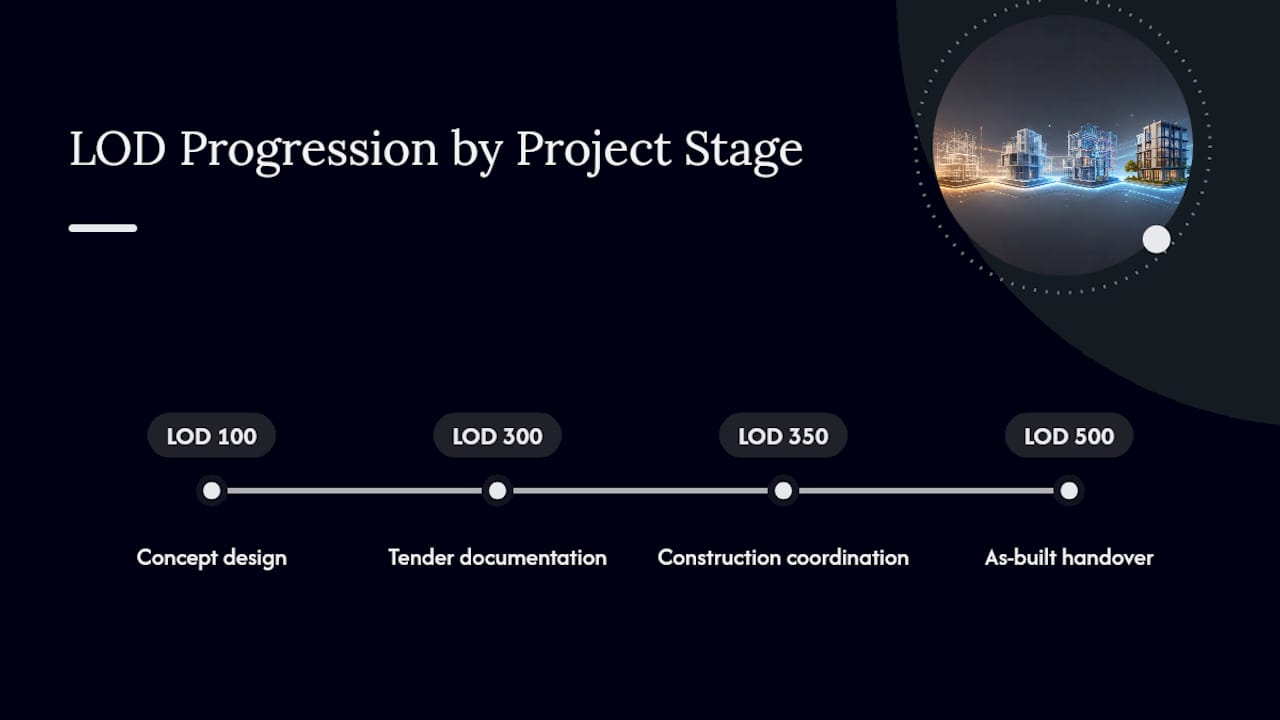
Project milestones may follow a progression of LOD levels such as concept design at LOD 100, tender documentation at LOD 300, construction coordination at LOD 350, and as-built handover at LOD 500.
Tools and Software That Support Managing and Verifying BIM LOD
Most major BIM authoring platforms now build LOD tracking directly into their workflows rather than treating it as an external spreadsheet exercise. Revit and similar authoring tools let you tag element parameters with current LOD status, so a reviewer can filter a model by level instead of inspecting each object individually. Coordination platforms built for federated model review flag clashes and let teams attach acceptance notes tied to specific LOD milestones.
Autodesk’s own guidance recommends pairing model authoring software with a dedicated LOD matrix tracked outside the model, since spreadsheets remain easier for whole project teams, including non-modelers, to review and sign off on. BIMForum’s Part II spreadsheet template serves the same purpose: a shared, editable record of author and LOD assignment per element that doesn’t require BIM software to open.
For verification at fabrication stages, shop-drawing production software checks geometry against manufacturer specifications before elements go to the shop floor, catching LOD 400 gaps before they become physical rework. Whatever combination you use, the software matters less than the discipline of checking every deliverable against its matrix entry at every milestone, not just at final handover.
How Does BIM LOD Affect Project Cost and Schedule Estimates?
LOD level directly shapes how much you can trust a quantity takeoff or a schedule duration pulled from a model. A cost estimate built on LOD 100 massing is a rough order-of-magnitude figure at best, useful for feasibility, dangerous if treated as a budget.
Once elements reach LOD 300, quantities become reliable enough for tender-stage pricing, since dimensions and locations are confirmed rather than assumed. Pushing critical trade elements to LOD 350 before construction starts catches clashes and connection problems on screen instead of on site, where fixes cost far more in both money and schedule delay.
Requesting LOD 400 detail late in a project, after subcontractors have already priced their scope at LOD 300 assumptions, is one of the most common sources of change orders. That’s exactly why documenting LOD requirements early, and funding upgrades as explicit scope changes, protects both budget and timeline. A project that treats LOD as an afterthought tends to pay for that decision twice: once in rework, and again in schedule float burned resolving disputes about what the model was supposed to show.
AECTechnicalSG’s Practical Checklist for Implementing LOD in Your BEP
Drop this sequence into your next BEP as a starting framework, then adjust it to your project’s actual complexity.
- Define project milestones and assign a target LOD to each one.
- Map every major element or system to a named model author.
- Set explicit, testable acceptance criteria for each target LOD.
- Tag elements in the model with their current LOD status.
- Schedule model reviews at each exchange milestone, not just at handover.
- Confirm FM acceptance and as-built verification before final sign-off.
Teams juggling authority submissions alongside model coordination often benefit from outside technical support, particularly on shop drawings and BIM execution planning where trade-specific detail is required.
Why Most Teams Get LOD Backwards
The conventional advice treats LOD as a modeling problem, something the BIM manager configures and everyone else ignores. That’s backwards. LOD is fundamentally a contract and communication problem wearing a technical costume. The BIMForum Specification and AIA’s definitions exist because teams kept arguing about what a model “should” contain, and nobody had language precise enough to settle it.
Where most projects fail isn’t in understanding what LOD 350 means. It’s in never writing target levels into the BEP at all, then discovering mid-project that the structural model everyone assumed was coordination-ready was actually still LOD 300. Fix the sequencing problem first: define your matrix at kickoff, assign authorship honestly, and treat every LOD upgrade request as a documented scope change. Everything else, the software tags, the review schedules, the acceptance checks, is just execution once that foundation exists.
If you need help translating LOD requirements into submission-ready documentation for Singapore’s regulatory bodies, that’s a narrower and more solvable problem than most teams expect. Start with the matrix. Everything downstream gets easier.
— Aman
Building an LOD matrix and BEP language that actually holds up through construction and authority submission takes more than a template. AECTechnicalSG’s engineering consultancy services help project teams translate BIM Level of Development requirements into coordinated structural, geotechnical, and M&E deliverables that meet submission standards from first draft.
Sources
- Level of Development (LOD) Specification
- What Is Level of Development (LOD) in BIM? A Complete Guide | AIA Contract Documents
- Levels of Development (LOD) in BIM | Autodesk
- What are LOD levels — how they impact your 3D BIM model? | Trimble