
The most damaging common engineering design plan mistakes are coordination failures across MEP, structural, and architectural disciplines; incomplete geotechnical site data; ambiguous specifications; inadequate QA and peer review; constructability gaps; overreliance on design software; insufficient structural detailing; designs that lag behind current codes; uncontrolled client-driven scope changes; and weak change management. Each one translates directly to rework, change orders, or schedule slippage. The good news: most are preventable within the first week of a project if the right controls are assigned to the right people.
Immediate 24–72 hour actions to reduce near-term risk:
- Assign a named owner to every open design discipline interface and confirm they have the current drawing set.
- Run a BIM clash detection report and log every hard and soft clash with a resolution deadline.
- Confirm geotechnical deliverables are scoped, contracted, and on schedule before foundation design advances.
- Issue a stop-the-line check on any drawing package that lacks a current revision stamp and approval signature.
- Prepare a standard clarification RFI template so ambiguous specification items can be escalated without delay.
Each mistake carries a specific cost mechanism. Coordination failures produce construction change orders when trades collide in the field. Missing site data forces foundation redesign mid-construction. Ambiguous specs generate disputes over scope and cost. Weak QA allows errors to compound until they reach the field, where correction costs multiply. Constructability gaps mean contractors must improvise, which introduces unauthorized deviations. Software overreliance lets input errors propagate undetected through entire calculation packages. Poor structural detailing creates connection failures. Code noncompliance triggers plan-check rejections and resubmittals. Client-driven scope changes without formal change notices erode both schedule and fee. All of these are preventable with the structured controls described below.
Key Takeaways
Preventing common engineering design plan mistakes requires upstream controls on coordination, site data, specifications, and change management, applied consistently from project mobilization through construction documents.
| Point | Details |
|---|---|
| Coordination failures drive change orders | Run BIM clash detection at every design milestone and assign a named resolution owner to every hard clash. |
| Geotechnical errors force the costliest rework | Incorrect soil investigation has forced redesign of more than 10% of a foundation in documented cases; verify boring depth and report recommendations before foundation design begins. |
| Ambiguous specs generate scope disputes | Reconcile every specification section against the drawing schedule before issuing a construction document package. |
| Peer review must be independent | Assign a checker who did not contribute to the design and require a written finding report, not a markup. |
| Change management protects schedule and fee | Implement a formal change-request template with a two-stage approval and a design freeze window at each major milestone. |
Table of Contents
- How do coordination failures between MEP, structural, and architectural disciplines happen?
- What site data and geotechnical gaps cause the most expensive rework?
- How do ambiguous specifications and document inconsistencies create scope disputes?
- Why does ignoring constructability lead to costly field changes?
- What does an implementable QA/QC and peer-review process look like?
- Where does overreliance on design software create the most risk?
- What structural detailing and load-path checks prevent the most failures?
- How do you keep designs current with codes and authority requirements?
- How should teams manage client-driven scope changes to protect schedule and budget?
- How do design mistakes translate to project cost and schedule impacts?
- A prioritized prevention checklist for design teams
- What does research say about which stakeholders contribute most to design errors?
- The real cost of skipping the checklist
- Sources
How do coordination failures between MEP, structural, and architectural disciplines happen?
Coordination failures are the single most frequent source of construction change orders on building projects. Practitioner research identifies specific omissions that consistently trigger delays: missing sequences of operation for HVAC systems, missing fire alarm panels and pull stations, strobes not coordinated with architectural reflected ceiling plans, undersized electrical circuits, and absent plumbing valves or floor drains. These are not exotic errors. They appear on project after project because disciplines work in silos, exchange drawings asynchronously, and rarely verify that their assumptions about adjacent systems are still valid after the other discipline has revised its own package.
The root cause is almost always an interface-control problem, not a competence problem. A structural engineer sizes a beam, an MEP engineer routes ductwork through the same zone, and neither knows the other has changed their model since the last coordination meeting. By the time the conflict surfaces in the field, the structural steel is already fabricated and the ductwork is on order.
A workable coordination routine has four components. First, establish a weekly interdisciplinary coordination meeting with a fixed agenda: open clashes from the BIM model, pending interface decisions, and upcoming drawing releases. Second, require each discipline lead to sign off on a coordination matrix that maps every major system interface, from structural penetrations to electrical panel locations to plumbing chase clearances. Third, run a formal BIM clash detection report at each design milestone (schematic, design development, construction documents) and resolve every hard clash before the package advances. Fourth, assign a single coordination lead, typically the project engineer or BIM manager, who owns the clash log and has authority to hold a drawing release until conflicts are resolved. For M&E coordination specifically, specialist consultancy input at the design development stage catches the majority of MEP-structural conflicts before they reach the construction document phase.
Pro Tip: In congested mechanical rooms and ceiling plenums, establish routing priority rules in writing before any discipline begins detailed design: structure governs, then gravity drainage, then large-bore mechanical, then electrical conduit, then low-voltage. Require a minimum 12-inch maintenance corridor alongside any equipment that needs periodic service access, and flag any zone where that clearance cannot be achieved for a prefabrication or access-corridor solution before the design is released.
What site data and geotechnical gaps cause the most expensive rework?
Geotechnical and site-data errors sit at the top of the cost-impact hierarchy because they are discovered late, during foundation construction, when correction requires demolition and reconstruction rather than a drawing revision. Empirical research surveying 243 design professionals found that errors in geological survey documents are a significant contributor to design errors, and that incorrect soil investigation has, in at least one reported case, forced redesign and reconstruction of more than 10% of a foundation. That is a concrete, documented consequence, not a theoretical risk.

Plan-check correction letters repeatedly flag the same geotechnical deficiencies: insufficient boring depth for the proposed structure, borings located too far from the building footprint to be representative, missing expansion index tests on expansive soils, incomplete drainage calculations, and geotechnical reports that describe soil conditions without providing clear design recommendations tied to the actual structural system. Each deficiency generates a correction cycle that delays permit issuance and, if not caught at plan check, surfaces as a field problem.
Site-verification checklist for geotechnical packages:
- Boring depth: confirm borings extend at least 1.5 times the anticipated stress influence depth below the lowest foundation element.
- Boring spacing: verify borings are located within the building footprint and at corners or load-concentration points, not only at the site perimeter.
- Lab tests: confirm expansion index, consolidation, shear strength, and permeability tests are specified for the soil types encountered.
- Design recommendations: verify the report provides explicit bearing capacity values, settlement estimates, and lateral earth pressure parameters keyed to the proposed foundation type.
- Drainage: confirm surface drainage calculations and subdrain recommendations are included where groundwater or expansive soils are present.
- Site visit: require the geotechnical engineer of record to conduct at least one site visit during foundation construction to verify conditions match the report.
For simple one- or two-story structures on known, uniform soils, a minimum of two borings with standard penetration testing and a basic lab suite is a reasonable floor. Mid-size commercial projects warrant a grid of borings at no more than 50-foot spacing with full lab characterization. Complex structures, hillside sites, or sites with fill history require a phased investigation: a preliminary phase to characterize variability, followed by a targeted phase once the structural system is defined. Mandatory site visits during design are not optional for any of these scales; desktop analysis alone consistently misses undocumented obstructions, buried utilities, and existing foundation elements that redirect the entire structural solution.
How do ambiguous specifications and document inconsistencies create scope disputes?
Ambiguous specifications are the primary mechanism by which scope disputes enter a project. When a specification says “provide a pump of adequate capacity” without stating flow rate, head, efficiency, or motor size, every contractor reads it differently. When the specification conflicts with the drawing schedule, the contractor picks the interpretation that costs less, and the owner pays for the difference through a change order.
The most common sources of ambiguity are missing performance criteria (what the system must achieve, not just what it must contain), unspecified accessories and ancillaries (isolation valves, pressure gauges, access panels), and direct conflicts between the drawing notes and the project manual. A specification that says “stainless steel fasteners throughout” while the structural drawings call out galvanized hardware creates a dispute that is entirely avoidable.
Sample clarification phrasing for RFIs and contract amendments:
- “Clarify whether the pump schedule on Sheet M-201 governs over Section 23 21 13 where flow rates differ. Confirm which document takes precedence and issue a revision to the other.”
- “Specification Section 26 27 26 does not specify the NEMA enclosure rating for panels in wet locations. Confirm NEMA 4X is required and issue an addendum.”
- “Drawing A-301 shows a 36-inch door at Room 114; the door schedule on A-601 shows 32 inches. Confirm the governing dimension and revise the inconsistent document.”
Document control is the structural backbone of specification integrity. Every drawing and specification must carry a current revision number, a revision date, and an approval stamp from the engineer of record. RFIs must be logged in a numbered register with a response deadline and a record of which documents were revised as a result. A single source of truth, whether a project management platform or a controlled document register, prevents teams from working from superseded drawings. M&E submission packages benefit particularly from a pre-submission cross-check that compares drawing schedules against specification sections line by line before the package is released.
Pro Tip: Before issuing any construction document package, run a three-column reconciliation: list every system or assembly in the specification, confirm it appears on at least one drawing with a clear reference, and confirm the drawing note matches the specification requirement. Any row with a blank cell is a potential change order.
Why does ignoring constructability lead to costly field changes?
Constructability failures occur when a design that is structurally and mechanically correct cannot be built as drawn without extraordinary cost, unsafe temporary conditions, or physical impossibility. Common examples include steel connections that require bolting in positions with no wrench clearance, precast elements that cannot be lifted without exceeding crane capacity at the required radius, and mechanical equipment specified for a room that has no access path large enough to move it through.
A constructability review must cover four categories: physical access (can the equipment and materials reach the installation point?), tolerances (are the specified tolerances achievable with standard construction methods?), temporary works (has the design accounted for shoring, formwork, and bracing during construction?), and lifting and handling (are rigging points, weights, and crane positions identified for heavy elements?).
Constructability review cadence:
- Schematic design (30% complete): Contractor or construction manager reviews the structural and MEP concept for major access and sequencing conflicts. Output: a written list of constructability concerns with suggested alternatives.
- Design development (60% complete): Contractor reviews detailed structural and MEP layouts for tolerance, access, and temporary works issues. Output: a marked-up drawing set with resolution notes.
- Construction documents (90% complete): Final constructability check focused on connection details, equipment access, and sequencing notes on drawings. Output: a signed constructability confirmation or a list of outstanding items.
Attendees at each review should include the design lead, the structural engineer of record, the MEP lead, and the contractor’s superintendent or project engineer. The design team retains decision authority, but the contractor’s field knowledge is the primary input.
The structural engineer redesigned the connection as a bolted end-plate detail at no additional cost to the owner, saving an estimated three weeks of field time.
Pro Tip: For any element weighing more than 5 tons or requiring installation in a confined space, require the structural engineer to include a construction sequence note and a rigging diagram on the drawing. This single requirement eliminates the majority of lifting-related constructability disputes.
- Verify that all mechanical equipment can be moved from the delivery point to the installation location through existing or planned openings.
- Confirm that formwork and shoring loads are within the capacity of the supporting structure at each construction stage.
- Check that specified concrete cover and reinforcement spacing are achievable with the specified aggregate size and vibrator access.
What does an implementable QA/QC and peer-review process look like?
A peer review is not a second opinion. It is a structured, independent check of the design by a qualified engineer who was not involved in producing it, with a defined scope, a written finding, and a sign-off record. The distinction matters because informal reviews, where a colleague glances at a calculation package and says it looks fine, provide no real protection and create false confidence.
The Hyatt Regency walkway collapse is the most cited historical example of what happens when shop drawing changes are treated as informal. A connection change that shifted load transfer from a single rod to a stacked-rod configuration doubled the load on the fourth-floor connection box beam. No independent structural analysis was performed on the revised detail. The walkway collapsed, killing 114 people. The lesson is not subtle: any change to a structural element, whether on a primary drawing or a shop drawing, requires independent verification before implementation.
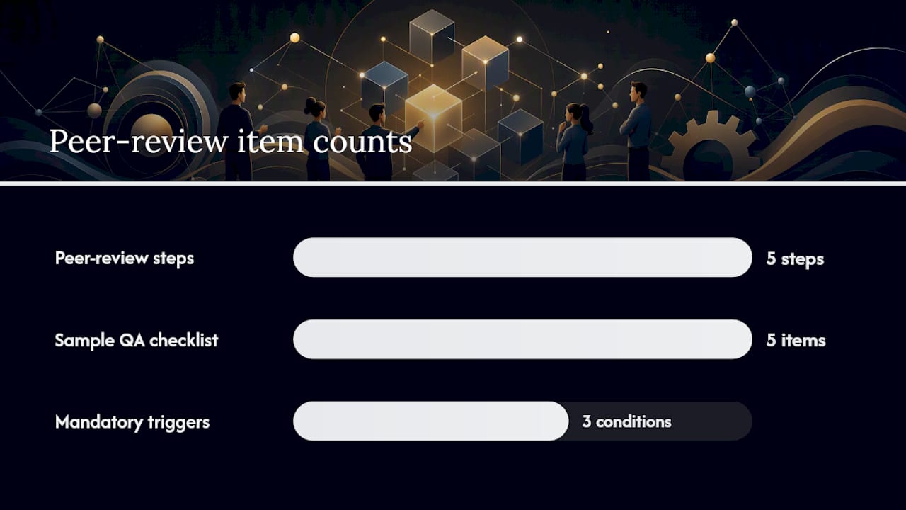
A practical peer-review process for building projects has five steps. First, define the review scope in writing: which calculations, which drawing sheets, and which load cases are in scope. Second, assign an independent checker who has not contributed to the design and has equivalent or greater qualification to the designer. Third, the checker performs an independent analysis, not a markup of the designer’s work. Fourth, findings are documented in a written report with a numbered finding list and a required response from the design team. Fifth, the design lead signs off that all findings have been resolved before the package is released.
Sample QA checklist items for calculation packages:
- Load combinations checked against the governing code edition.
- All member sizes verified against the calculation output, not assumed from a previous project.
- Connection details checked for the maximum demand from the analysis, not the minimum code requirement.
- Boundary conditions in the structural model verified against the actual support conditions shown on drawings.
- Seismic and wind load paths traced from the roof diaphragm to the foundation.
Independent design checks should be mandatory for any structure classified as Risk Category III or IV under ASCE 7, any project with a structural system that deviates from prescriptive code provisions, and any project where a single connection failure could produce progressive collapse. For design safety assurance, the peer-review scope should be defined at project kickoff, not added as an afterthought when the design is nearly complete.
Pro Tip: Schedule the peer review at 90% construction documents, not at 100%. A review at 100% creates pressure to accept findings without adequate time to resolve them. At 90%, the design team still has a revision cycle available.
Where does overreliance on design software create the most risk?
Design software is a productivity tool, not a verification tool. The most dangerous software pitfall is not a bug in the program; it is an engineer who accepts the output without understanding whether the inputs were correct. Structural design mistakes frequently arise from faulty analysis inputs, wrong boundary conditions, and misuse of software defaults, all of which produce results that look numerically precise but are physically wrong.
Common software pitfalls and their consequences:
- Default units: Analysis software switched between metric and imperial units mid-project has produced member designs that are undersized by a factor of 4.45 (the pound-to-Newton conversion). Always confirm the unit system at model setup and again before extracting results.
- Wrong boundary conditions: A column modeled as pinned at the base when the foundation detail provides moment fixity, or vice versa, changes the effective length factor and the design moment demand. Verify boundary conditions against the actual connection detail, not the software default.
- Auto-routed services: MEP software that auto-routes ductwork and conduit will route through structural members, fire-rated assemblies, and inaccessible ceiling spaces if no constraints are set. Auto-routing output requires manual review against the structural and architectural model before it is treated as a coordinated layout.
- Blind acceptance of code-check outputs: A “pass” flag from a code-check module confirms that the member satisfies the code equations as the software has interpreted them. It does not confirm that the load path is correct, that the connection is designed, or that the deflection is acceptable for the actual finish system.
Manual validation steps that catch the majority of automated-model errors include: a hand-calculation spot-check of the most heavily loaded member using simplified tributary-area methods; a boundary-condition review comparing the model support conditions to the foundation drawing; and a load-path trace from the roof to the foundation using only the structural drawings, without reference to the model output.
What structural detailing and load-path checks prevent the most failures?
Structural failures in practice rarely originate from undersized members. They originate from undetailed or incorrectly detailed connections, missing load-path elements, and insufficient redundancy. A beam sized correctly for bending can still fail if the bearing length at the support is inadequate, if the shear transfer path to the diaphragm is not detailed, or if the blocking required to transfer lateral load between framing members is shown on the drawing but not dimensioned or specified.
Load-path checklist:
- Gravity loads: trace from roof dead and live load through each framing level to the foundation. Confirm every transfer element (beams, girders, columns, bearing walls) is sized for the accumulated load.
- Lateral loads: trace seismic and wind forces from the roof diaphragm through the lateral system (shear walls, moment frames, braced frames) to the foundation. Confirm collector elements and drag struts are sized and detailed.
- Connection details: confirm every connection shown on the drawings has a design basis, either a standard connection from a referenced table or a project-specific calculation. Connections shown as “typical” without a defined load limit are a liability.
- Redundancy: confirm that the failure of any single element does not produce progressive collapse in a Risk Category III or IV structure. Alternate load paths should be identifiable from the drawings.
Common omission points that appear repeatedly in peer-review findings include: bearing lengths at masonry or concrete supports not called out on the drawing; shear transfer paths at diaphragm discontinuities not detailed; blocking at roof-to-wall connections shown in section but not in plan; and anchor bolt patterns for equipment not coordinated with the structural slab design. Each of these is a one-line addition to a drawing that prevents a field RFI or, in the worst case, a structural deficiency.
How do you keep designs current with codes and authority requirements?
Code noncompliance at plan check is one of the most predictable and avoidable sources of project delay. The International Building Code, ASCE 7, ACI 318, AISC 360, and their state-adopted amendments are updated on regular cycles, and the adopted edition varies by jurisdiction. A design team that applies the 2018 IBC to a project in a jurisdiction that has adopted the 2021 edition will receive plan-check corrections on every code-dependent calculation and detail. Building code compliance is not a one-time check at project start; it requires a named owner and a documented update process throughout the design.
Procedural controls for code currency:
- Assign a named code-compliance owner for each project at kickoff. This person is responsible for confirming the adopted code edition with the authority having jurisdiction (AHJ) before design begins.
- Maintain a project code tracker: a one-page document listing each applicable standard, the edition adopted by the AHJ, and the date confirmed. Update it whenever a design milestone is reached.
- Subscribe to update bulletins from ASCE, ACI, AISC, and the relevant state building department. When a new edition is adopted mid-project, assess the impact on completed design work and document the assessment.
- Include a code compliance statement on the title sheet of every drawing package: list each applicable standard by title and edition, the jurisdiction, and the date of AHJ confirmation.
A pre-application meeting with the plan-checking authority before final submission is one of the highest-return investments a project team can make. Plan checkers will identify local amendments, ADA requirements, and utility conflict issues that are not visible from the published code alone. For projects with unusual structural systems or occupancy classifications, a formal code interpretation request before design completion eliminates the risk of a fundamental compliance dispute at plan check.
How should teams manage client-driven scope changes to protect schedule and budget?
Uncontrolled client intervention is a documented root cause of design errors. The same multi-stakeholder research that identified geotechnical errors as a major cause of rework also found that client input errors are a significant upstream contributor to design mistakes. When a client directs a design change verbally, without a formal change notice, the design team lacks documented basis for the additional cost, record of the technical review that should accompany the change, and protection if the change produces a downstream problem.
A defensible change-management workflow requires four elements. First, a change-request form that captures the change description, the requester, the date, the technical impact assessment, the cost estimate, and the schedule impact. Second, a two-stage approval: technical review by the engineer of record, followed by commercial approval by the project manager and the client’s authorized representative. Third, a design freeze window at each major milestone, during which no client-directed changes are accepted without a formal change notice and a schedule impact assessment. Fourth, a change log that is shared with the client at each progress meeting so the cumulative impact of approved changes is visible.
Headers for a change-request template:
- Change Request Number
- Date Submitted
- Requested By (client representative name and authority)
- Change Description
- Technical Impact (disciplines affected, drawings to be revised)
- Cost Estimate (design fee and construction cost impact)
- Schedule Impact (days added to the milestone)
- Technical Review Sign-off (engineer of record)
- Commercial Approval Sign-off (project manager and client)
- Freeze Window Status (within freeze: yes/no)
When a client requests a change during a freeze window, the correct response is not refusal but documentation: acknowledge the request, record it in the change log, and schedule it for the next open change window unless it involves a safety issue that requires immediate action.
How do design mistakes translate to project cost and schedule impacts?
Design errors do not cost what they cost to fix on paper. They cost what they cost to fix in the field, under time pressure, with trades already mobilized. A drawing revision that takes two hours at the design stage can require three weeks of field rework if the error is discovered after concrete is placed or steel is erected.
Common cost drivers from design rework:
- Extended general conditions: every week of schedule delay adds supervision, site overhead, and equipment rental costs.
- Change order premium: field changes carry a contractor markup, typically 15–25% above direct cost, for overhead and profit on the additional work.
- Delayed handover: late project completion triggers liquidated damages in many contracts and delays the owner’s revenue from the facility.
- Redesign fees: the design team may absorb redesign costs for errors of omission, but disputed errors generate claims that cost more to resolve than the underlying rework.
A simple framework for estimating contingency based on risk category:
A risk register for engineering projects should carry at minimum: a risk description, the probability (low/medium/high), the consequence (minor/moderate/major), the risk owner, and the mitigation action. Reviewing the risk register at each design milestone keeps the team focused on the items most likely to produce cost and schedule impact.
A prioritized prevention checklist for design teams
The following checklist is organized by urgency. Items in the immediate category should be completed within 72 hours of project mobilization or upon identifying a gap mid-project. Near-term items belong in the current design sprint. Project-wide controls are standing requirements for the duration of design.
Immediate (24–72 hours):
- Confirm the geotechnical scope is contracted and the boring program is approved.
- Run a BIM clash detection report and assign a resolution owner to every hard clash.
- Verify the current code edition with the AHJ and record it in the project code tracker.
- Confirm every discipline lead has the current drawing set with the correct revision number.
- Issue a standard RFI template to the team for ambiguous specification items.
Near-term (current sprint):
- Schedule the first interdisciplinary coordination meeting and set a recurring cadence.
- Complete the site-verification checklist and confirm a site visit is scheduled.
- Assign a peer-review lead and define the review scope in writing.
- Distribute the change-request template to the client and confirm the approval workflow.
- Run a specification-to-drawing reconciliation for the current package.
Project-wide controls:
- Maintain a live clash log with resolution status and responsible party.
- Update the risk register at every design milestone.
- Require a constructability review sign-off at 60% and 90% design completion.
- Log every RFI with a response deadline and a record of resulting document revisions.
- Conduct a pre-application meeting with the AHJ before final submission.
Responsibility assignments:
| Role | Owns |
|---|---|
| Design Lead | Drawing release, specification reconciliation, peer-review scope |
| QA Lead | Clash log, RFI register, code tracker, risk register |
| Geotechnical Engineer | Boring program, site visit schedule, report recommendations |
| Client Representative | Change-request approvals, freeze window acknowledgment |
For high-risk items, the escalation path is: design lead identifies the issue, QA lead logs it in the risk register, project manager notifies the client, and the engineer of record makes the technical determination. No high-risk item is resolved by field personnel without written authorization from the engineer of record.
What does research say about which stakeholders contribute most to design errors?
The most rigorous available evidence on this question comes from a survey of 243 design professionals that examined the causation of design errors from a multi-stakeholder perspective. The study found that client input errors and errors in geological survey documents are among the most significant contributors to design mistakes, alongside noncompliance with applicable standards.
The practical implications are direct. Design input controls must be treated as a design activity, not an administrative one. A versioned design-input package, with a named owner and a formal review before design begins, is the upstream control that prevents the majority of client-related errors from entering the design. Geotechnical scope must be defined by the structural engineer of record, not delegated to the client or the geotechnical firm alone, because the structural engineer is the only party who knows what design parameters the report must deliver.
Key implications for project practice:
- Require a formal design-input review meeting at project start, with the client, the geotechnical engineer, and the design lead present.
- Limit informal client direction on technical matters to a documented request that triggers the change-management workflow.
- Require the geotechnical engineer of record to confirm that the report’s recommendations are sufficient for the proposed structural system before foundation design begins.
- Treat noncompliance with survey standards as a design risk, not a contractor issue, and verify compliance before accepting the geotechnical report.
The study’s evidence is drawn from design professionals’ self-reported experience, which introduces recall bias, and the findings may not generalize uniformly across all project types and scales. The directional conclusion, that client inputs and geotechnical data quality are high-leverage upstream controls, is consistent with practitioner guidance and plan-check correction patterns observed across multiple jurisdictions.
The real cost of skipping the checklist
The pattern that appears most consistently across project postmortems is not a single catastrophic error. It is a sequence of small omissions, each individually manageable, that compound into a project-defining problem. A coordination meeting skipped because the schedule was tight. A geotechnical report accepted without verifying that the boring depth matched the foundation type. A client’s verbal direction implemented without a change notice because the relationship felt too important to formalize. A shop drawing approved without an independent structural check because the deadline was tomorrow.
The Hyatt Regency walkway collapse is the most sobering example of where that pattern leads. The connection change that caused the collapse was not the result of ignorance. It was the result of a process that treated a structural revision as informal, as something that did not require the same independent analysis as the original design. The engineers involved were not incompetent. The process failed them, and 114 people died.
Most design errors do not produce catastrophic failure. They produce change orders, schedule slippage, and disputes that consume months of management attention and erode client relationships. The prevention tools described in this article, coordination routines, geotechnical verification, specification reconciliation, peer review, constructability checks, and change management workflows, are not bureaucratic overhead. They are the minimum process discipline that separates a project that delivers from one that litigates.
The recommended next step is concrete: assign an owner to each of the five immediate checklist items above, set a 72-hour deadline, and run the BIM clash report before the end of the week. For teams that need integrated engineering consultancy support to implement these controls across disciplines, specialist input at the design development stage is the most cost-effective point of intervention.
Sources
- The Causation of Design Error in the Construction Industry: A Multistakeholder Perspective
- 10 Most Common Building Design Phase Mistakes – Facilities Management Insights
- Plan Check Corrections: Common Issues and How to Avoid Them | Moment Engineering
- Site verification and constructability guidance (PDHOnline course material)
- The Hyatt Regency walkway collapse