
Introduction
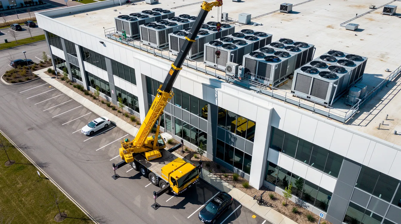
Lifting heavy chiller units onto existing roofs demands far more than a capable crane and a competent lifting team. Every heavy equipment rigging lifting plan for rooftop HVAC installations must begin with a fundamental question: can the existing roof slab safely carry the concentrated forces from crane outriggers, staged equipment, and dynamic lifting loads? Without verified answers backed by engineering data, the risks involved escalate rapidly-from structural cracking to catastrophic slab failure.
This operational guide covers the full scope of PE-endorsed crane mat design, slab capacity verification, and temporary loading assessments for chiller installations on existing buildings in Singapore. It addresses how to prepare a comprehensive lifting plan, how to assess structural adequacy, and how to select the right equipment and load-spreading solutions. Topics outside this scope-such as permanent mechanical system design, chiller commissioning, or new-build structural design-fall beyond these boundaries.
The target audience includes contractors managing complex lifts, facility managers overseeing chiller replacements, and building owners planning new HVAC installations on existing structures. Whether you are coordinating a single load replacement or managing complex projects involving multiple units, the structural risks remain the same.
A proper lifting plan requires structural engineer verification that existing slabs can handle crane outrigger loads, equipment staging loads, and dynamic lifting forces-supported by PE-endorsed calculations, crane mat specifications, and BCA-compliant temporary works documentation.
After reading this guide, you will understand:
-
PE endorsement and regulatory requirements for temporary works in Singapore
-
How to assess existing slab capacity against crane outrigger and staging loads
-
Crane mat sizing calculations and material selection criteria
-
Dynamic load factors and safety margins required for rigging operations
-
Step-by-step implementation procedures from initial assessment to BCA submission
Understanding Structural Loading Requirements
Every existing building was designed to carry specific categories of loads. When a crane lift operation introduces forces that the original designers never anticipated, the structure may be pushed beyond its capacity. Understanding these load categories-and how they differ from temporary heavy equipment loading-is essential before any rigging plan can proceed.
Dead loads are the permanent weights the structure carries continuously: the roof slab’s own weight (reinforced concrete at approximately 24 kN/m³ means a 200mm slab contributes roughly 4.8 kN/m² from concrete alone), plus reinforcement, roofing finishes, parapets, and curbs. Live loads (also called imposed loads) account for temporary occupancy weights-people, maintenance equipment, and stored materials. In Singapore, these are governed by SS EN 1991-1-1 and the BCA Approved Document, with typical roof maintenance loads in the range of 1.5–2.0 kN/m².
Temporary construction loads-the category most relevant to this guide-include crane self-weight, outrigger reaction forces, load weight from chiller units being staged, dynamic effects from lifting and slewing, and even wind forces acting on suspended loads. These temporary loads are not part of the original building design unless specifically considered under actions induced by cranes and machinery per SS EN 1991-3:2010. The difference between what a slab was designed for and what a crane operation demands is where structural risk concentrates.
PE Endorsement Requirements for Temporary Works
Singapore’s regulatory framework requires Professional Engineer involvement whenever temporary works may affect structural capacity. Under the Building Control (Temporary Buildings) Regulations, temporary works including protective structures and equipment staging require compliance verification. The Workplace Safety and Health (Operation of Cranes) Regulations 2011 explicitly mandate an approved lifting plan for any mobile crane with SWL exceeding 5 tonnes or any tower crane operation.
For temporary works in Singapore, standards such as E/GD/09/104/A2 require that all temporary works are designed, certified, and checked by a PE, with method statements, drawings, and calculations independently verified. A risk assessment is an important part of every lifting plan to identify hazards that could compromise structural integrity or personnel safety. The JTC Space Submission Handbook further requires PE (civil) endorsement for equipment exceeding 400 kg in tenanted premises-a threshold that every chiller unit far exceeds.
The explicit connection to liability is direct: failure to secure proper PE structural endorsement exposes contractors and building owners to regulatory enforcement, potential fines under WSHA, and full liability for any structural damage or serious incidents. Personnel roles must be clearly designated in the lifting plan for effective operation, and every appointed person and decision maker in the chain must understand their responsibilities.
Slab Capacity vs Equipment Loading
The gap between original design loads and crane-imposed loads is often dramatic. A roof slab designed for a uniform imposed load of 3–5 kN/m² may face a single outrigger pad delivering 300–500 kN over an area smaller than one square meter. This concentrated force creates bending moments and punching shear stresses that the slab reinforcement was never sized to resist.
Key elements determining a slab’s resistance to these concentrated loads include slab thickness, concrete grade (typically 25–40 MPa for existing buildings), reinforcement layout (top and bottom bars, stirrup spacing), span between supporting beams, and whether the floor system is flat slab, ribbed, waffle, or composite. Allowable bearing pressures might range from 150–500 kN/m² depending on these factors, but these values must be derived through detailed structural analysis-not assumed.
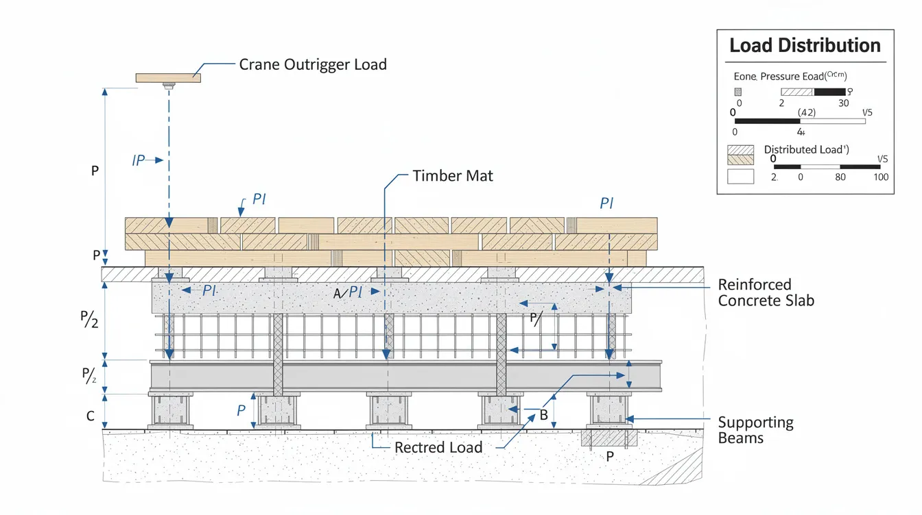
The load path from a chiller lift runs through every structural element: from the chiller through slings and other lifting gear to the crane hook, through the crane structure to outriggers, through crane mats to the slab, then into beams, columns, and foundations. Each link in this chain must be verified. Understanding this relationship between slab capacity and equipment loading is what makes crane mat design not just a logistics decision, but an engineering imperative.
Crane Mat Design and Load Distribution
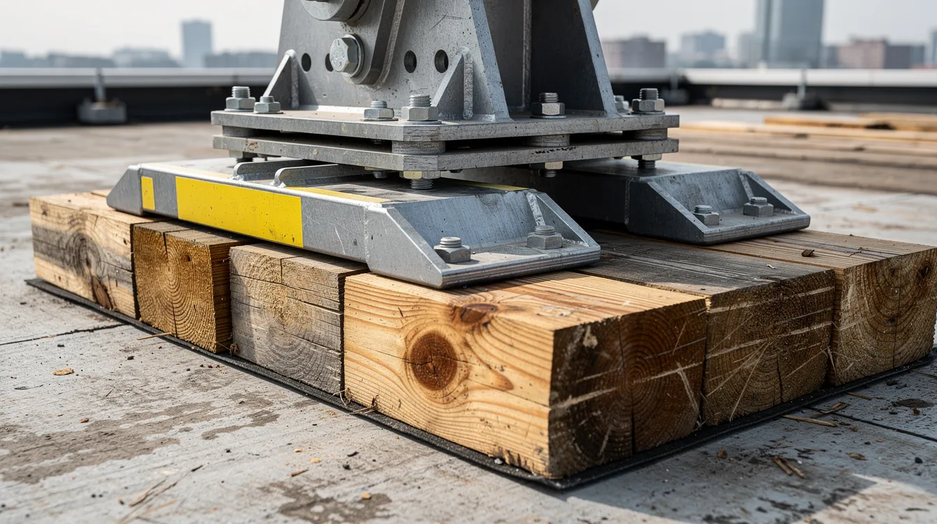
With slab capacity principles established, the engineering challenge becomes practical: how to distribute concentrated crane forces across enough slab area to keep stresses within safe limits. Crane mats are the primary load-spreading devices used to bridge the gap between outrigger point loads and slab bearing capacity, with crane and rigging equipment specifications forming part of the load-spreading design basis. Their design directly determines whether a crane lift can proceed safely on an existing roof.
Calculating Point Load Distribution
A lifting plan is a documented plan for how a lift will be performed safely, and the crane mat sizing calculation sits at its core. The fundamental equation is straightforward: the required pad area must equal or exceed the outrigger reaction force (ORF) divided by the allowable bearing pressure of the supporting slab.
For timber crane mats-the most common solution for temporary works-sizing involves determining the maximum ORF from the crane manufacturer’s load charts for the specific boom length, radius, and outrigger configuration. If a crane generates an ORF of 400 kN and the slab’s allowable bearing pressure is 200 kN/m², the minimum mat area required is 2.0 m². In practice, safety factors of 2.0 or greater are applied, increasing the required area. The mat must also be positioned so its contact area falls over structurally supported slab panels-ideally spanning across beams or column supports rather than centering on unsupported slab spans.
Steel plate alternatives offer greater rigidity and can span gaps or weak zones more effectively. Steel plates deflect minimally under load, allowing more predictable load distribution, but they are significantly heavier and more expensive to transport and install. They also carry higher risk of damaging slab surfaces through point contact unless a protective layer (grout bed, neoprene padding) is placed beneath. The material choice depends on load weight, site conditions, and equipment availability. A comprehensive lifting plan includes load weights, rigging arrangements and site conditions to inform this selection.
Crane Selection and Positioning Analysis for Lifting Operations
Crane selection for rooftop chiller lifts involves analyzing how crane capacity charts change with outrigger extension and boom configuration. At greater boom radii, the crane’s safe working load decreases while outrigger reaction forces increase-precisely the wrong combination for slab loading. The crane operator must work within configurations that balance lift capacity against structural constraints of the supporting surface.
Positioning the crane so outriggers align over primary structural elements-beams, column lines, or thickened slab sections-transfers loads more directly into the building’s load path. Placing outriggers near slab edges, cantilevered sections, or over penetrations introduces potential hazards that proper planning must address. The site layout must account for boom swing radius, any adjacent-structure height restriction, and exclusion zones around the lifting area, since limited headroom may require an alternative crane configuration. A lift plan should include exclusion zones to ensure safety around the lifting area, protecting both personnel and structural elements.
Ground conditions must be verified to ensure they can support crane loads-and on a rooftop, “ground” means the existing slab system, which may have concealed deficiencies. Load charts provided by the crane manufacturer assume a rigid, level, infinitely strong support surface; the structural engineer must verify that reality matches these assumptions.
Dynamic Load Factors
Static load weight alone does not tell the full story. During any lifting operation, accelerations from hoisting, slewing, braking, and wind create dynamic forces that magnify the effective load. SS EN 1991-3 provides characteristic values for vertical crane-induced actions and horizontal forces from acceleration, which are applied as dynamic factors to the static outrigger reactions.
Environmental conditions such as wind speed limits must be established for safe lifting. Wind acting on a suspended chiller unit adds lateral loads that change the outrigger force distribution and can increase the critical outrigger reaction well beyond static values. Impact effects from sudden load release or sling slackening create transient spikes that the slab must absorb. Consistent overloading-even momentary-can lead to crane failure or tipping incidents.
Design load combinations per Eurocode standards require considering dead load plus live load plus crane loads plus wind, each with appropriate partial safety factors (1.0 for permanent loads, 1.35–1.5 for variable loads). The controlling combination produces the design envelope that crane mats and slab capacity must satisfy.
Key load distribution principles to carry forward: every outrigger reaction must be distributed to allowable bearing pressures through appropriately sized mats; dynamic factors increase static loads by 10–30% or more; and the structural engineer must verify capacity under the most unfavorable combination of loads.
Structural Analysis, Risk Assessment, and Implementation Procedures
Moving from crane mat design principles to actual project execution requires a systematic approach. Effective rigging lift plans minimize human error and prevent structural failures, but only when the underlying structural analysis is thorough and the implementation follows verified procedures.
Step-by-Step Slab Assessment Process
A detailed structural assessment is required whenever lifting equipment imposes loads that may exceed the original design capacity of the supporting structure-which is nearly always the case for mobile crane operations on existing roofs. Load weight must be determined before lifting operations, and the following process ensures nothing is overlooked.
-
Gather existing structural documentation. Obtain original structural drawings, as-built information, and any alteration records. Key data includes slab thickness, reinforcement details (top and bottom bars, spacing, cover), beam locations and sizes, column positions, and foundation type, and where relevant the review should identify available lifting points on the chiller unit or supporting frame for the planned lift. For buildings where documentation is incomplete, field investigation including concrete core sampling and reinforcement scanning may be required. Understanding when structural endorsement is required helps determine the extent of documentation needed.
-
Assess material properties. Verify concrete compressive strength (f’c), reinforcement yield strength, and modulus of elasticity. For older buildings, assumed values from original specifications may not reflect actual conditions. Core testing and rebar identification provide the engineering data needed for reliable calculations. This step is critical-plans must identify load weight and center of gravity, but the structure’s actual capacity is equally important.
-
Calculate allowable temporary loading. Using the verified material properties, determine the slab’s bending moment capacity, shear capacity, and punching shear resistance under concentrated loads. Compare these against the distributed outrigger loads (ORF divided by mat area) plus the slab’s own dead load and any existing live loads. The analysis should follow methods consistent with BCA structural calculation requirements-strip method or grillage analysis for load distribution, with punching shear checks around each pad perimeter.
-
Verify crane outrigger loads against distributed mat loading capacity. Cross-reference the crane manufacturer’s outrigger reaction data (for the chosen boom length, radius, and lift weight) with the slab’s verified capacity. Include dynamic load factors per SS EN 1991-3. The rigging configuration and sling selection must suit lifting points and the verified center of gravity. If any outrigger location exceeds the slab’s capacity even with mats, reposition the crane or specify larger mats to span additional structural bays.
-
Prepare PE-endorsed temporary works calculations and drawings for BCA submission. The final deliverable is a detailed document including the site layout showing crane position, mat placement, reaction forces, load paths, and rigging configuration, and it should also define project-specific control measures and assess site impact before work begins. Rigging plans must be reviewed by a competent person-in Singapore’s regulatory context, this means a registered PE. Submission to BCA or relevant authorities may be required for significant temporary structural changes affecting public safety. Each lifting operation should start with a pre-lift safety briefing for all personnel involved, referencing this documentation.
Communication methods and protocols must be established before a lifting operation begins. The method statement should specify who communicates what, through which channels, and the stop-work triggers if site conditions deviate from assumptions.
Crane Mat Specification Comparison
Selecting appropriate rigging gear and load-spreading solutions requires comparing options against specific project constraints. The following table summarizes key differences for different loading scenarios:
|
Criterion |
Timber Mats |
Steel Plates |
Composite / Hybrid Mats |
|---|---|---|---|
|
Weight per area |
Light to moderate; easier to transport to rooftop locations |
Heavy; requires additional crane capacity for placement |
Lighter than steel; benefits in constrained access scenarios |
|
Rigidity & Deflection |
Moderate deflection under heavy loads; risk of fiber crushing |
Very rigid; minimal deformation; predictable load spread |
Variable; stiff options available but edge support critical |
|
Damage Risk to Slab |
Lower risk; more forgiving contact surface |
Higher risk of point contact damage without protective layer |
Minimized with proper hybrid design |
|
Cost |
Lower upfront; widely available and easy to source |
Higher material and logistics cost |
Highest per-unit cost; justified for repeated use or weight constraints |
|
Best Application |
Moderate ORF values; temporary single-use lifts; limited access |
High point loads; repeated lift campaigns; minimal footprint required |
Weight-restricted roofs; frequent repositioning; long-term projects |
Use timber mats when crane operations are temporary, access logistics are limited, and loads are moderate. Specify steel plates or composite solutions where heavy point loads are expected, mat footprint must be minimized, or the site demands repeated lift safely operations over extended periods. The center of gravity of each mat assembly should be considered during placement to ensure stable seating on the slab surface.
Common Challenges and Solutions
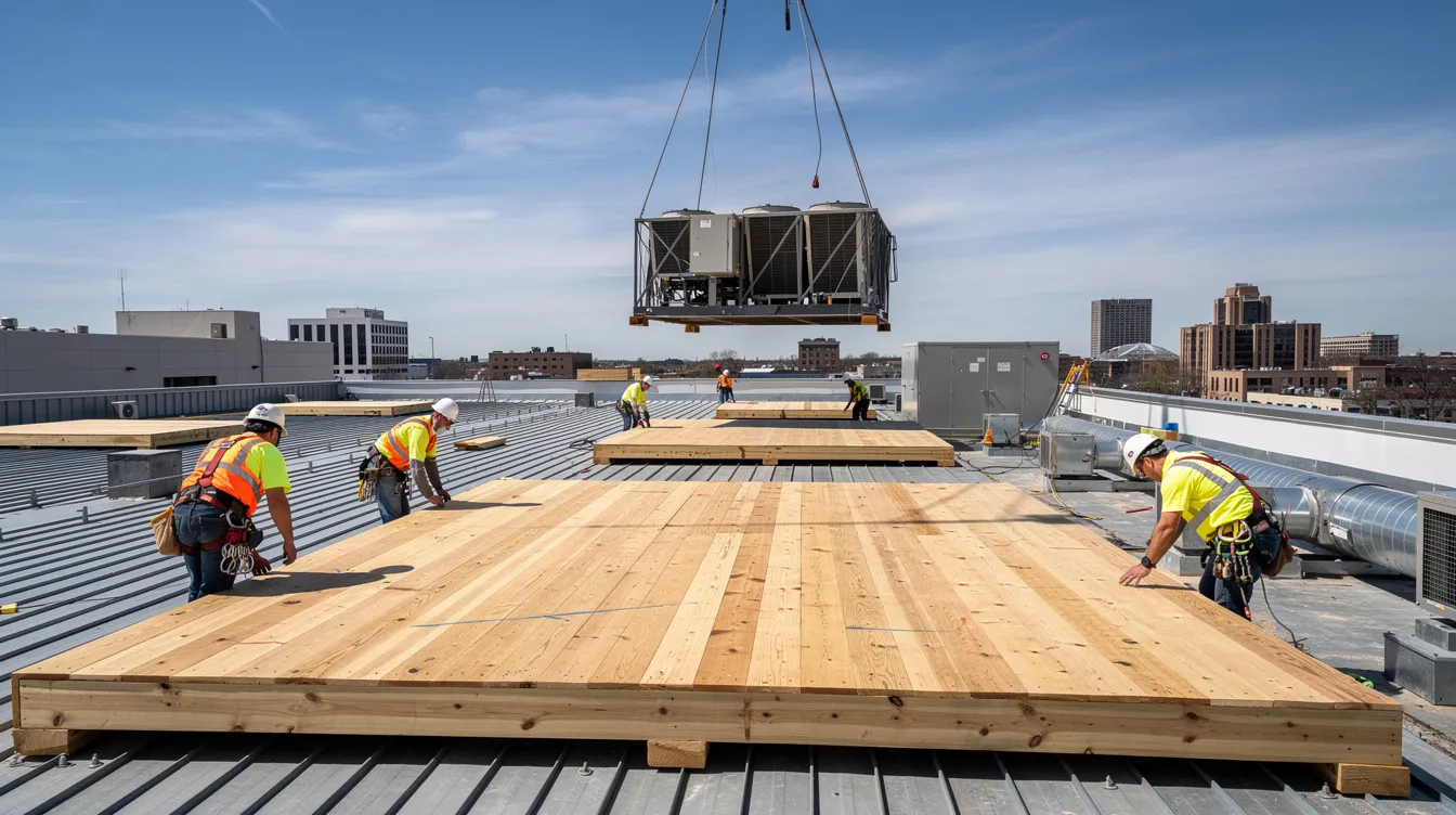
Rooftop chiller lifting operations on existing buildings routinely encounter obstacles that require engineering judgment and creative problem-solving. Improvising deviations from the rigging plan can cause incidents-every challenge must be addressed through documented, PE-verified solutions before work begins. Rigging plans must include load weight and center of gravity for each lifted element, and these challenges directly affect how those parameters interact with the structure.
Insufficient Slab Capacity for Direct Crane Placement
This is the most frequent challenge. Slabs designed for occupancy loads cannot handle outrigger forces, failing in either bending or punching shear. In Jaberson Technology’s chiller replacement project in Singapore, two 43,000 kg chillers required replacement, but the parking area designated for crane setup was a cantilevered slab unable to bear the outrigger forces. The solution involved deploying load-spreading steel beams beneath crane mats to distribute outrigger pressure across multiple structural bays. All calculations and proposals were verified by a Qualified Person.
When slab capacity remains insufficient even with enhanced load distribution, consider alternative approaches: relocating the crane to ground level (if boom reach permits), using a tower crane with foundations independent of the roof structure, or delivering chillers in CKD (complete knockdown) configuration to reduce individual lift weights. Lifting loads over 50 tons requires a detailed rigging plan, and splitting units into modules can bring individual lifts below critical thresholds. A critical lift is one where additional planning or controls are warranted due to high consequences-and insufficient slab capacity defines that condition precisely.
Limited Roof Access for Large Mobile Cranes
Many existing buildings were not designed with rooftop equipment replacement in mind. Narrow access roads, height restrictions from overhead utilities, adjacent structures limiting boom swing, and limited deck area for outrigger deployment all constrain crane selection. The difference between what the project requires and what can physically reach the installation point defines this challenge.
Solutions include using compact spider cranes that can be transported through building interiors and assembled on the roof, selecting mobile cranes with asymmetric outrigger configurations that fit available space, or-for the most constrained sites-helicopter lifts that bypass access limitations entirely. OSHA requires qualified riggers for certain construction activities involving lifting, and the competency requirements for these alternative methods may exceed standard crane lift qualifications. Equipment selection must balance crane capacity against access constraints, with the rigging plan adapted accordingly. Each option carries different preparation requirements for temporary works and PE endorsement needs.
Existing Roof Penetrations, Utilities, and Rigging Gear Considerations
Rooftops are rarely empty. Skylights, mechanical plant room walls, ductwork, cable trays, and-critically-waterproofing membranes occupy space that crane mats and outriggers need. Placing mats across expansion joints, over penetrations, or on damaged waterproofing creates both structural and envelope risks. Site conditions must be assessed before lifting operations commence, and coordination with MEP trades is essential.
The solution requires early coordination between the structural engineer, roofing contractor, and MEP consultants. Crane mat placement must avoid penetrations and joints; if unavoidable, custom steel grillage designs can span across weak zones while bearing on structurally adequate sections. Protective coverings-plywood sheets, neoprene pads, geotextile layers-should be specified beneath all mats to preserve waterproofing integrity. The cost of repairing waterproofing failures or leaks post-lift can significantly exceed the cost of prevention, making this coordination a control measure that ensures both safety and budget adherence. Building owners should also understand how construction works can affect structural safety beyond the immediate lift operation.
Rigging equipment must be inspected prior to each lifting operation, and this extends to the temporary support infrastructure-mats, spreader beams, and protection layers should be checked for damage, displacement, or degradation before every crane lift sequence. A competent lift supervisor must review rigging plans and verify that on-site conditions match the documented assumptions. Accurate CoG identification prevents lifting operation instability, and the center of gravity is critical for load stability of every chiller unit throughout the rigging procedure.
Conclusion, Method Statement, and Next Steps
Every rooftop chiller installation on an existing building presents a structural verification challenge that cannot be shortcut. The load path from crane outrigger through mat to slab to beam to column must be analyzed, documented, and PE-endorsed before any crane mobilizes. Effective rigging and lifting plans-integrating slab capacity analysis, crane mat design, dynamic load factors, and BCA compliance-are what separate safe, successful operations from potential hazards and identified hazards that lead to structural damage or worse.
To ensure optimal safety and regulatory compliance for your next rooftop chiller project, take these immediate steps:
-
Engage a structural PE early-before requesting crane contractor quotations. Discovering slab inadequacy after mobilization creates expensive delays and safety exposure. Understanding what a PE signs off on helps set expectations for this engagement.
-
Gather all existing building structural drawings, including slab plans, reinforcement details, beam layouts, loading history, and any modification records.
-
Coordinate with your crane contractor to obtain outrigger reaction force data for all feasible boom configurations, including dynamic factors and maximum dimensions of the lifting equipment.
-
Develop a comprehensive method statement covering crane positioning, mat layout, rigging procedures, exclusion zones, communication protocols, and weather contingencies. A formal lift plan documenting each of these following elements ensures every team member understands their role.
-
Schedule pre-lift briefings for all personnel-crane operator, riggers, signalman, and supervisors-covering the approved lifting plan, necessary precautions, potential risks, and stop-work criteria.
Related topics worth exploring include construction method statement development, MEP coordination for rooftop installations, ongoing structural monitoring during extended rigging operations, and design for safety principles that should inform every complex lift from project inception.
Additional Resources
-
BCA Approved Document – Acceptable solutions for structural design and construction, including imposed load requirements and temporary works provisions (BCA guidelines)
-
SS EN 1991-3:2010 – Actions induced by cranes and machinery, with Singapore National Annex for computing vertical and horizontal crane forces on supporting structures
-
Workplace Safety and Health (Operation of Cranes) Regulations 2011 – Lifting plan requirements, personnel qualifications, and crane operation safety standards (WSHA Regulations)
-
JTC Space Submission Handbook – PE endorsement requirements for equipment installation in tenanted industrial premises (JTC Handbook)
-
For structural engineering consultation on temporary works, slab loading analysis, and PE endorsement for heavy equipment lifting operations, AEC Technical Advisory provides specialist support across Singapore’s construction and facilities management sectors