
M&E coordination drawings are the final, clash free drawings that installation teams build from on-site, produced by overlaying mechanical, electrical, and plumbing systems against architectural and structural models until every conflict is resolved. Their core purpose is preventing rework: BIM-driven clash detection catches interferences before pipes and ducts are fabricated, and standards like SS 553 and NBIMS anchor the process in defined roles and formats.
TL;DR:
- Coordination drawings include detailed, scaled models of ductwork, cable trays, and support systems, all verified for clash-free installation.
- Clear roles like project manager, spatial coordinator, and subcontractors are essential to prevent delays and unresolved conflicts during coordination.
- Clash detection must be iterative, starting with up-to-date, accurate models, and should focus on structural and architectural freezing stages first.
- Sign-off only occurs after all trades have clash-free systems signed in the coordinated set, with deviations leading to rework costs.
- Maintaining a detailed issue log and following strict procedural checks at each milestone reduces common coordination errors like mismatched standards and late model uploads.
Table of Contents
- What Do M&E Coordination Drawings Actually Include?
- Who Handles What in the Coordination Process?
- How Does BIM Clash Detection Turn Into Buildable Drawings?
- How Should You Plan the Coordination Schedule and Sign-Off?
- Which Standards Govern M&E Coordination in Singapore?
- Checklist: Producing and Reviewing Coordination Drawings You Can Actually Build From
- What Goes Wrong Most Often, and How Do You Fix It?
- An M&E Consultant’s View on Making Coordination Work
- Get Coordination-Ready Drawings Without Chasing Multiple Consultants
- Sources
- FAQ
What Do M&E Coordination Drawings Actually Include?
A finished coordination set is not a single drawing. It’s a package that carries every discipline’s routing, hardware, and clearances at a scale detailed enough to build from.
Expect these components in a properly assembled set:
- Modeled major components at scale: ductwork, cable trays, sprinkler mains, and equipment shown at their true dimensions, not schematic placeholders.
- Annotated installation drawings: plan and section views marked with elevations, offsets, and dimensions trades need on-site.
- Hanger and support details: locations and types coordinated so no two trades claim the same ceiling space.
- Service risers: vertical shaft coordination showing how each system stacks floor to floor.
- Access and maintenance clearances: space reserved for filter changes, valve access, and future servicing.
Deliverables usually arrive as coordinated native model files, PDF installation drawings for the field, a signed coordination sign-off set, and shop drawings ready for fabrication. Consistent file naming and matched view scales across disciplines matter more than most teams realize. A single mislabeled revision can send a fabricator back to cut ductwork against an outdated riser. Our guide on M&E engineering documentation covers naming and archival conventions in more depth.
Who Handles What in the Coordination Process?
Coordination fails most often when nobody owns a specific task. NBIMS spatial coordination requirements assign distinct roles precisely to avoid that gap:
- Project Coordination Manager (PCM): builds and enforces the coordination schedule, chairs meetings, and tracks whether milestones tied to fabrication lead times are being hit.
- MEP Spatial Coordinator (MSC): compiles discipline backgrounds, runs clash detection passes, and issues clash reports along with updated model files after each cycle.
- MEP subcontractors: model their own major components at the required level of detail, attend meetings, and sign off on the final installation drawings once conflicts clear.
- Design team: steps back in whenever a clash can’t be resolved without changing the original design intent, such as a beam depth that forces a duct reroute.
Clear role assignment, backed by the NBIMS MEP spatial coordination requirements, keeps a coordination schedule from drifting into finger pointing when a clash turns up late.
How Does BIM Clash Detection Turn Into Buildable Drawings?
The workflow starts with what the design team hands over. MEP coordination can’t begin properly without architectural and structural models (or CAD backgrounds where BIM isn’t fully adopted) that are current and dimensionally accurate. Feeding stale backgrounds into a coordination model is one of the fastest ways to burn a coordination cycle on conflicts that don’t actually exist anymore.
From there, clash detection runs iteratively rather than as a single pass:
- Each round produces a clash report listing hard clashes (physical overlaps) and soft clashes (clearance violations).
- Level of Detail (LOD) shapes what decisions are even possible at a given stage; you can’t finalize hanger spacing against an LOD 200 duct model.
- Reports need an owner assigned to each clash line, not just a flagged conflict sitting unresolved between meetings.
Pro Tip: Sequence your clash detection rounds so structural and architectural elements freeze first. Chasing MEP clashes against a moving structural grid wastes coordination hours that never come back.
Weekly meetings with a running action log resolve clashes faster than monthly reviews, since unresolved items compound instead of clearing. Our streamlined M&E workflow guide walks through LOD progression stage by stage, which matters if your team is still deciding what to model at each phase.
How Should You Plan the Coordination Schedule and Sign-Off?
A coordination schedule needs to be tied to real construction milestones, not an abstract design timeline. Fabrication lead times for ductwork, sprinkler mains, and switchgear should set the deadline for when a coordinated model freezes, working backward from the install date.
Meeting discipline is what actually protects that schedule:
- Attendance should be mandatory for every trade with an active clash in the current report.
- Action items need a named owner and a due date, recorded and circulated the same day.
- Meeting minutes and clash logs should be stored where every party can reference them later, not buried in one coordinator’s inbox.
Coordination sign-off drawings get signed by each trade once their systems are clash-free in the coordinated set. That signature carries weight: the standard convention is that any party installing work that deviates from the signed drawings bears the cost of rework, a principle the NBIMS coordination requirements make explicit.
Which Standards Govern M&E Coordination in Singapore?
Two references do most of the heavy lifting for coordination teams working locally.
SS 553 sets minimum requirements for ACMV design, installation, testing, and commissioning. Edition matters more than most teams assume: the 2026 revision reorganized design clauses and updated inputs like outdoor air conditions and filter requirements, which changes the assumptions baked into duct sizing and equipment selection.
On average, drawings that omit a stated standard edition create ambiguity during procurement, since two proposals drawn to different SS 553 editions aren’t actually comparable, even when they look similar on paper, according to practical commentary on SS 553.
The NBIMS MEP spatial coordination requirements round out the picture on the process side, covering minimum file formats, required annotations, and mandatory meeting cadence.
Practical takeaways worth building into your tender documents:
- Require every design consultant to state the standard edition and specific clauses their design was prepared against.
- Confirm file format compatibility across disciplines before coordination begins, not after the first clash report.
- Cross-check ACMV assumptions (outdoor air, occupancy loads) against the edition cited on the drawing title block.
Where exhaust or kitchen extraction ducts intersect environmental permitting, NEA’s e-services handle the relevant pollution control filings.
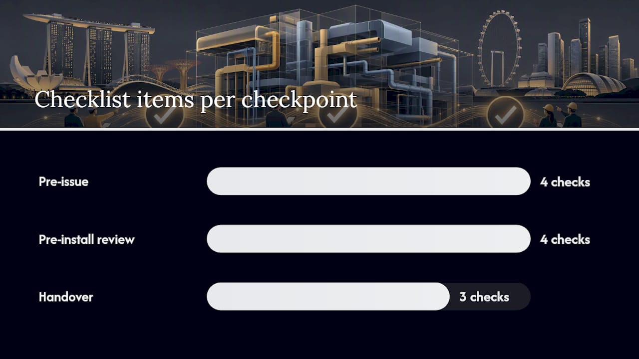
Checklist: Producing and Reviewing Coordination Drawings You Can Actually Build From
Most coordination disputes trace back to a shortcut taken at one of three checkpoints. Run through these before anything moves to the field.
- Pre-issue: confirm model completeness across every discipline, verify hangers and supports are modeled (not just the pipes and ducts they carry), check riser alignment floor to floor, and validate maintenance clearances against equipment access requirements.
- Pre-install review: verify the set is genuinely clash-free, confirm the coordination sign-off has every trade’s signature, distribute both the native model and PDF drawings, and check that fabrication notes match what’s shown in the coordinated views.
- Handover: compile a record of every issue raised and how it was resolved, assign as-built update responsibility to a named party, and archive the full coordination history, not just the final signed set.
Pro Tip: Keep the issue log even after sign-off. When a facility manager opens a ceiling five years later and finds a duct that doesn’t match the drawing, that log is what tells them whether it was an approved field change or an installation error.
Our shop drawing production guide covers how coordinated drawings translate into fabrication-ready shop sets once this checklist clears.
What Goes Wrong Most Often, and How Do You Fix It?
A handful of mistakes account for most coordination failures on Singapore projects:
- Mismatched standard editions: one consultant designs to an older SS 553 edition while another assumes the current one, and nobody catches it until commissioning.
- Incomplete discipline models: a trade uploads a partial model, clash detection runs clean, and the missing components collide with everything else once they finally appear.
- Late model uploads: one late submission delays the entire coordination cycle for every other trade waiting on that background.
- Poor meeting attendance: unresolved clashes carry over week after week because the responsible trade never showed up to claim them.
The fix in each case is procedural, not technical: freeze a baseline model version at each milestone, issue immediate change notices when a discipline deviates from that baseline, set clear cost allocation rules before a dispute happens, and document every reconciliation in writing. Waiting until a clash becomes a site problem is the expensive way to learn these lessons.
An M&E Consultant’s View on Making Coordination Work
Coordination drawings only do their job when the team producing them treats the process as risk management, not paperwork. Projects that hand M&E design, BIM modeling, and shop drawing production to one accountable consultant tend to catch clashes earlier, because the same team that models the ductwork is also the team answering for the fabrication set. Authority submission work benefits from that same continuity: a coordinated set that already accounts for SS 553 compliance moves through review with fewer queries. The teams that struggle are usually the ones that split coordination, shop drawings, and submissions across parties who never sit in the same meeting.
— Aman
Get Coordination-Ready Drawings Without Chasing Multiple Consultants
Most project teams end up juggling a design consultant for M&E engineering, a separate drafter for shop drawings, and yet another party for authority submissions, and coordination gaps tend to open up exactly at those handoffs. Aectechnicalsg runs M&E engineering design, BIM modeling, and shop drawing production under one roof, so the model used for clash detection is the same model your fabricators build from.

That continuity is what clients should expect in practice: installation-ready coordination drawings, a fully signed shop drawing set aligned to the coordinated model, and direct support pushing the package through authority submissions once coordination closes out. If your current coordination process keeps stalling at the handoff between design and fabrication, get in touch through our services page and describe where the gap is happening.
Sources
- SS 553:2026 code of practice for air-conditioning and mechanical ventilation in buildings (preview)
- Difference between MEP drafting, MEP design & coordination drawings (CADProA)
FAQ
What Is the Difference Between M&E Design Drawings and Coordination Drawings?
Design drawings show each discipline’s intended layout in isolation, while coordination drawings overlay every system together to resolve physical conflicts before installation. The distinction between drafting, design, and coordination drawings is that only the coordinated set is meant to be built from.
Who Is Responsible for Signing Off on Coordination Drawings?
Each MEP subcontractor signs off once their systems are clash-free in the coordinated set, alongside the MEP spatial coordinator and project coordination manager. The NBIMS coordination requirements place rework costs on any party that installs work deviating from that signed set.
Why Does the SS 553 Edition Matter on a Coordination Drawing?
Each SS 553 revision updates design inputs like outdoor air conditions and filter requirements, so a drawing prepared to an outdated edition can carry incorrect ACMV assumptions. Stating the edition and clause references on the drawing avoids comparing proposals built on mismatched assumptions.
Can Aectechnicalsg Produce Coordination Drawings and Shop Drawings Together?
Yes. Aectechnicalsg offers M&E engineering design, BIM modeling, and shop drawing production as connected services, so the coordinated model feeds directly into the fabrication set rather than passing between separate consultants.
What Happens If a Trade Installs Work That Doesn’t Match the Signed Coordination Drawings?
The party responsible for the deviation typically bears the cost of rework, a principle built into the NBIMS coordination sign-off process. That’s why keeping a documented issue log through handover matters as much as the sign-off itself.