
Introduction
A Professional Engineer (PE) structural assessment is the first gate any factory owner in Singapore or Southeast Asia must pass before mounting a solar array on an existing metal roof. The assessment determines whether purlins and trusses can carry the added dead load of solar panels (typically 15–25 kg/m², or roughly 0.15–0.25 kN/m²), combined with wind uplift forces calculated at a basic 3-second gust speed of 33 m/s under CP 3 Chapter V Part 2, and any applicable seismic or live loads.
This article covers the full structural capacity evaluation process for metal roof solar mounting systems on industrial buildings: load calculation methodology, PE certification requirements, and the regulatory framework governing solar installation in Singapore. It is written for factory owners evaluating solar retrofits, solar developers scoping new projects, and engineering consultants preparing PE structural endorsements for BCA submission.
Solar PV mounting systems for factory metal roofs provide structural benefits and operational efficiencies when properly engineered. Load-bearing capacity of metal roofs must be precisely assessed before any PV system is installed, and system durability should be evaluated against its expected life expectancy; skipping or shortcutting this step risks structural failure, code violations, and voided roof warranties.
After reading this article, you will understand:
-
How factory roof load paths transfer solar panel weight to foundations
-
The dead load, live load, and wind uplift calculations a PE performs
-
Step-by-step PE evaluation procedures and certification requirements
-
Strengthening solutions when existing purlins or trusses fall short
-
BCA and SCDF regulatory thresholds triggering formal structural submission
Understanding Factory Metal Roof Solar Mounting Structural Systems
A factory metal roof is not a single element; it is a hierarchy of components, each carrying loads to the next, and attachment details vary across different types of metal roof systems. Solar panel mounts attach to roof panels, which span across purlins, which bear on primary trusses, which transfer loads through columns to foundations. Every link in that chain must have enough reserve capacity to handle the additional weight and wind forces from a PV array, with roof and attachment materials affecting how those loads are transferred and checked.
Purlin and Truss Load Paths
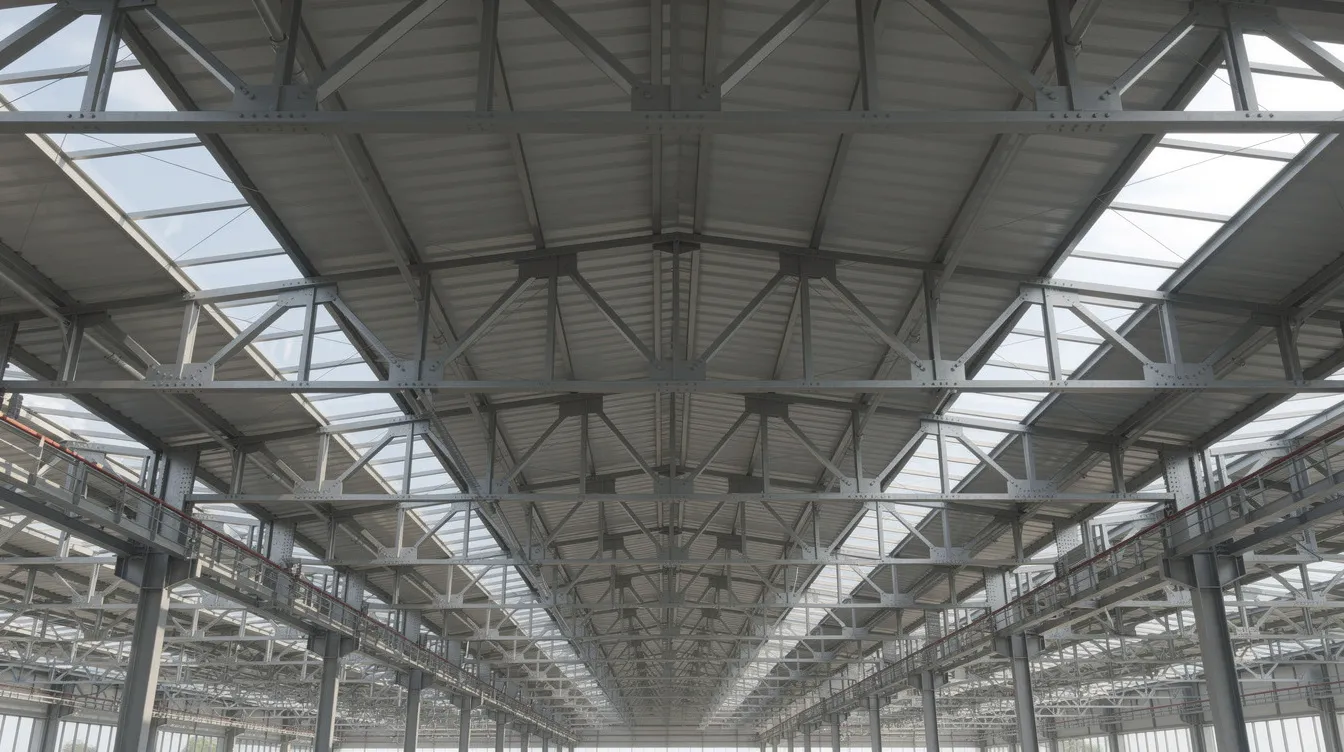
When you install solar panels on a metal roof, the mounting system transfers weight through clamps or brackets into the roof panel, then into the secondary purlins beneath. Purlins are typically cold-formed C or Z sections (or hot-rolled shapes in heavier industrial buildings) spanning between primary trusses at centers of 1.0–2.5 m. The trusses, which are large steel or welded built-up frames spanning 8–20 m between support columns, carry the cumulative purlin reactions down to foundations.
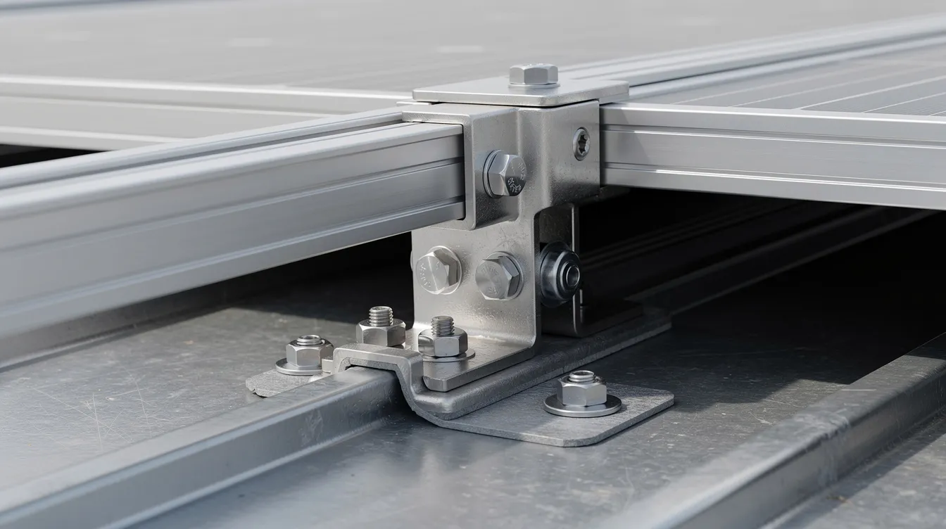
Weight distribution across structural ribs is crucial for the safe installation of solar panels on metal roofs. Point loads from mounting brackets concentrate forces at specific purlin locations; a PE must verify that both local bending at these points and global truss reactions remain within design limits. Installing rails for solar panels requires careful alignment with internal purlins to ensure stability, because attaching a rail between purlins loads the thin roof panel in a span where it was never designed to carry concentrated force.
Common Factory Roof Configurations
Three roof types dominate Singapore’s industrial building stock, and each dictates a different mounting approach:
Standing seam roofs (e.g., Klip-Lok profiles) feature raised seams that accept non-penetrating clamps. Standing seam clamps attach directly to raised seams without penetration, which preserves manufacturer roof warranties and eliminates leakage risk compared to traditional systems. Factory-approved accessories can also speed installation and support cable-management or safety details. In a Singapore project documented by S-5!, 848 panels (181 kWp) were installed on a ~2,000 m² Klip-Lok roof using S-5-K clamps with zero roof penetrations.
Trapezoidal metal roofs have flat pans between trapezoidal ribs. Mounting on these profiles often requires through-bolts or specialized fasteners that penetrate the roofing material. Proper sealing is essential for exposed fastener roof mounts; without it, using engineered designs helps prevent excessive costs from roof leaks and damage due to improper installations. Steel panels typically range from 22-gauge to 26-gauge material, thin enough that fastener torque values must meet local building codes to avoid crushing or deforming the profile.
Corrugated sheeting, common on older factories from the 1980s and 1990s, presents the most constrained scenario. The corrugation depth limits clamp grip strength, and the sheet gauge is often thinner than trapezoidal profiles. Engineers recommend purlin spacing of 70–120 cm for corrugated iron systems to maintain adequate sheet support, which means older buildings with wider purlin spacing may need supplemental members before solar modules can be mounted.
Solar mounting systems must match specific metal roof profiles for optimal performance. A clamp designed for standing seam profiles will not grip a trapezoidal rib securely, and a bracket engineered for corrugated sheets will not fit standing seam profiles. This compatibility check is one of the first items a PE verifies before proceeding with load analysis.
Structural Load Assessment Methodology
With the roof system and profile type identified, the PE moves to quantifying every force the structure must resist once the solar array is in place.
Dead Load Analysis
Solar panel dead loads typically range from 15–25 kg/m² (0.15–0.25 kN/m²), covering the module, mounting rails, clamps, brackets, and any ballast. Lighter systems exist: the AEROCOMPACT FLAT-R system, deployed on a TPO membrane roof for an electronics manufacturing facility in Singapore, achieved a total system weight of just 11.8 kg/m² by using aluminum components and eliminating ballast.
These loads sit on top of the existing roof dead load. In a typical Malaysian industrial building, the roof sheeting plus insulation weighs approximately 25 kg/m² (0.25 kN/m²). Adding a solar system therefore increases the total dead load on purlins by 50–100%. Metal roofs are lightweight but require precise load assessments; the original design loads often left minimal reserve capacity because engineers sized purlins to the code minimum for the roof cladding alone.
Live Load Considerations
Maintenance access loads must be accounted for even after PV panels cover the roof surface. Singapore’s building code provisions typically require a minimum imposed load of 0.25 kN/m² or higher for roof access zones.
Wind uplift is the dominant lateral force on rooftop solar arrays, but designers should also check vertical design effects on the mounting system and roof support. PV panels act as sails; wind flowing over and under tilted modules generates uplift pressures that try to peel the mounting system off the roof. Solar mounting hardware must be accurately engineered to handle wind uplift and structural loads, and compatible brackets may also be needed to securely attach conduit or cable-management elements to the roof. Improper wind load calculations can lead to panel displacement, and this risk is elevated in coastal factory locations where exposure categories increase the design wind pressure. BCA requires wind actions per Singapore’s national annex of SS EN 1991-1-4, using the 33 m/s basic gust speed.
Fire safety regulations must be considered when installing solar systems on industrial roofs in Singapore. The SCDF Fire Code 2023, clause 10.2 limits array dimensions to 60 m × 40 m and requires 3 m clearances around rooftop hatches and exit doors.
For regions outside the tropics, snow loads must also be factored in. A 3 to 4-foot space is recommended for snow retention systems to prevent sliding accumulation from damaging lower panel rows or roof edges.
Existing Structural Capacity Verification
The PE must establish what the roof was originally designed to carry. This involves three activities:
Drawing review. Locate original as-built drawings to confirm truss spans, purlin profiles, material grades, connection details, and original design loads. Many older factories lack accurate documentation, forcing the PE to adopt conservative assumptions.
Field inspection. Measure purlin cross-sections with calipers, check connection bolt sizes, inspect for corrosion-related section loss, and note any modifications or repairs since construction. Even when dimensions appear adequate on paper, corrosion at joints and along purlins can reduce effective capacity by 20–40% in buildings exposed to tropical humidity for decades.
Material testing. When documentation is missing or unreliable, non-destructive testing (hardness testing, ultrasonic thickness measurement) or destructive coupon tests may be needed to confirm steel or other roof materials, as well as remaining wall thickness.
The results of this verification feed directly into the PE’s capacity calculations, where each purlin and truss member is checked against the combined loading from existing dead load, solar system dead load, live loads, and wind uplift.
Detailed PE Capacity Analysis Procedures
Once field data and load inputs are assembled, the PE executes a structured analysis to certify whether the roof can accept the proposed solar mounting system or requires strengthening.
Step-by-Step Structural Evaluation Process
A comprehensive PE analysis is required whenever a factory owner plans to install solar panels on an existing industrial roof. In Singapore, structural plan submission becomes mandatory when supporting structure height exceeds 2.5 m or canopy areas exceed 10 m², per JTC’s Solar Deployment Guide 2026.
-
Original structural drawing review and code verification. The PE compares the building’s original design loads against current code requirements (SS EN 1991-1-4 for wind, BCA Approved Document for load combinations). Buildings designed in the 1980s under older British Standards may have lower wind load provisions than current Eurocode-based requirements.
-
Field inspection of purlin condition, connections, and structural integrity. The PE documents corrosion depth, bolt condition, weld integrity, and any visible deflection. Purlins in coastal factories (e.g., Tuas industrial zone) often show accelerated corrosion despite excellent corrosion resistance ratings of original galvanized coatings, because the service life of zinc coatings in marine environments can be 15–25 years rather than the 40+ years assumed for inland locations.
-
Solar mounting load calculation. The PE models point loads from each bracket or clamp, distributed loads along rails, and net wind uplift on the PV array at the specified tilt angle; in some rail-based systems, an L-Foot connects the roof attachment to the rail, and its connection behavior must be reflected in the load path analysis. Systems designed for metal roofs must accommodate thermal movement due to temperature changes; metal roofs expand and contract with daily and seasonal temperature cycles, and the mounting system must allow this thermal expansion without overstressing fastener holes or clamp connections.
-
Structural adequacy check. Using limit state design (Eurocode) or allowable stress design (British Standards), the PE verifies bending moment capacity, shear capacity, deflection limits, and connection strength for each purlin and truss member under the combined load case. Preparing BCA structural calculations for submission requires documenting each check with load diagrams, member capacities, and utilization ratios.
-
PE certification and strengthening recommendations. The PE issues a signed certification of structural adequacy or specifies required strengthening works, with the selected mounting solution also checked for compatibility with the roof’s expected service life and overall life expectancy. For buildings needing BCA submission, the PE’s calculations and drawings form the core of the regulatory package.
Critical Wind Uplift Analysis Parameters Comparison
Factory roof structural capacity varies with building age and original design intent. The table below summarizes typical differences a PE encounters:
|
Analysis Factor |
Light Industrial (1980s–1990s) |
Heavy Industrial (2000s onward) |
|---|---|---|
|
Typical Purlin Spacing |
1.5–2.5 m centers |
1.2–1.8 m centers |
|
Original Dead Load Design |
Roof sheet + minimal insulation (~0.25 kN/m²) |
Higher allowance, sometimes solar-ready |
|
Truss Span |
8–12 m, lighter rolled sections |
12–20 m portal frames, heavier sections |
|
Solar Load Capacity |
Frequently requires strengthening |
Often adequate, but connections need verification |
|
Corrosion Risk |
Higher (30–40+ years of exposure) |
Lower (newer coatings, shorter exposure period) |
Older light industrial buildings almost always need purlin strengthening or supplemental supports. Newer heavy industrial buildings may have adequate member sizes, but the PE still verifies connection details and checks that the original design loads were not already fully consumed by existing imposed loads or equipment.
Singapore’s Green Mark NRB: 2015 scheme includes “Structural readiness” as an evaluation criterion, requiring roofs to be certified by a structural QP/PE for both static and wind loads from PV systems. This requirement has driven newer industrial buildings to allocate reserve structural capacity for future solar deployment.
Common Challenges and Solutions
PE assessments of factory roofs for solar upgrades consistently encounter the same set of structural and documentation issues.
Inadequate Purlin Capacity
When existing purlins cannot carry the additional dead load from solar panel mounts plus wind uplift, the PE specifies one of several strengthening approaches. The most common is adding supplemental C or Z sections alongside existing purlins, effectively doubling the local bending capacity. In cases where purlin spacing is too wide (2.5 m or more), additional intermediate purlins are installed between existing ones, bolted to the primary trusses. For detailed strengthening methodology on industrial roofs, AEC Technical has documented approaches in their guide on warehouse roof strengthening for large-scale solar panel installations.
Optimized metal roof mounting systems can reduce lifecycle costs by 28–30% when the mounting design is coordinated with the strengthening design. Aligning new purlin positions with mounting rail locations eliminates redundant members and reduces the total steel tonnage.
Missing or Incomplete Structural Drawings
Many older Singapore factories built in the 1980s lack original as-built drawings. The PE must then perform a full field survey: measuring every purlin and truss section, mapping bolt patterns, and sampling steel for grade verification through hardness testing.
Conservative assumptions apply throughout. If a purlin’s steel grade cannot be confirmed, the PE designs to a lower-bound grade (e.g., Grade 250 rather than Grade 350). This approach can result in additional strengthening that would not be needed if documentation existed, adding 10–20% to project cost. Factory owners planning solar retrofits should locate and preserve any original structural drawings before engaging a PE.
Roof Weathering and Corrosion Issues
Corrosion is the most common disqualifier for direct solar mounting on older metal roofs. Section loss at purlin flanges reduces bending capacity, while corroded bolt holes enlarge under load, weakening connections.
The PE’s condition assessment establishes the extent of corrosion and specifies remediation: localized section replacement, application of protective coatings, or full purlin replacement. In the Flows Ong project, a 185.475 kWp system was installed on a roughly 40-year-old metal roof after structural and load assessment confirmed adequacy; the PE recommended waterproofing works before installation to protect the aging roofing material from further degradation.
Non-penetrating mounting systems reduce leakage risk on aging roofs, which is why many PEs recommend standing seam clamps or ballasted systems for buildings where the roof panel integrity is questionable. Elimination of roof penetrations protects existing manufacturer roof warranties and prevents leaks; this is a decisive advantage for buildings approaching the end of their roof’s service life.
Thermal Expansion, Movement and Fastener Integrity
Metal roofing expands with temperature changes. In Singapore, roof surface temperatures can swing from 25°C at night to over 70°C under midday sun, causing linear expansion of several millimeters per meter of roof length. Mounting systems that rigidly lock to the roof sheet at multiple points can buckle the panel or shear fastener holes as the metal moves.
Proper torque values prevent roof damage during solar panel installation. A PE specifies torque ranges for each fastener type, matched to the roof panel gauge and material. Over-torquing a bolt into a 26-gauge steel panel crushes the profile; under-torquing allows the bracket to loosen under wind cycling. Purpose-built clamps designed for industrial profiles can reduce drilling and sealing work, shortening installation time while maintaining secure attachment through controlled compression rather than friction against a drilled hole.
Conclusion and Next Steps
PE structural assessment is not an optional formality; it is the engineering verification that determines whether a factory roof can safely carry solar panels for a 25-year service life under the combined forces of gravity, wind, maintenance loads, and thermal cycling. Skipping or abbreviating this assessment exposes building owners to structural failure risk, regulatory non-compliance with BCA and SCDF requirements, and voided roof warranties.
To move forward with a factory solar installation:
-
Locate existing structural drawings for the building, including any modification records from past renovations
-
Engage a qualified PE for a preliminary structural assessment to determine if the roof has reserve capacity or needs strengthening
-
Schedule a field inspection to document purlin and truss conditions, connection details, and corrosion extent
-
Coordinate with the solar installer to ensure the proposed mounting system is compatible with the roof profile and the PE’s load analysis
-
Prepare BCA submission documents if the installation triggers structural plan submission thresholds (supporting structure >2.5 m height or canopy >10 m²)
Related topics worth exploring include BCA submission requirements for building works, structural repair solutions for addressing corrosion-damaged members, and ongoing maintenance protocols for rooftop PV systems on industrial buildings.
Additional Resources
Singapore’s regulatory framework for industrial rooftop solar includes several overlapping requirements:
-
BCA Approved Document V7.06 governs wind load calculations at 33 m/s basic gust speed under CP 3 Chapter V Part 2
-
Green Mark NRB: 2015 requires structural readiness certification for buildings seeking Green Mark ratings
-
SCDF Fire Code 2023, Clause 10.2 specifies PV array dimension limits (60 m × 40 m) and access clearances (3 m around hatches and exit doors)
-
JTC Solar Deployment Guide 2026 establishes mandatory requirements for solar installations on JTC-managed industrial premises
Singapore’s national solar deployment target has been raised to 3 GWp, increasing regulatory and market pressure on factory owners to evaluate their roofs for solar readiness. Non-penetrating clamp systems reduce installation time by 10–15% compared to penetrative mounting, and installing solar mounting systems reduces installation time and labor costs by 30–50% compared to custom-fabricated supports. Elevated solar panel profiles can improve ventilation and energy efficiency during hot weather by creating a cooling effect between the panel and the roof surface, reducing the building’s internal temperature and lowering air conditioning electricity consumption.
Grounding systems are necessary to protect solar installations from electrical faults and lightning; the PE’s structural assessment should coordinate with the electrical engineer’s grounding design to ensure that grounding conductors are routed through the mounting system without compromising structural connections.
For factory owners and solar developers seeking PE endorsement and BCA submission support for industrial rooftop solar projects, engaging a structural engineering consultancy with experience in both warehouse roof strengthening and solar load analysis ensures that the assessment covers all code requirements and produces submission-ready documentation.