
The primary types of building envelope systems used in US practice are curtain wall and window wall, rainscreen and ventilated cladding, mass and monolithic walls, insulated concrete forms (ICFs), EIFS and composite cladding, masonry veneer and CMU, precast panels and tilt-up, prefabricated panel systems, double-skin façades, and green walls. Each system is defined by where it places the four continuous control layers: water, air, thermal, and vapor.
Selecting among these systems requires evaluating control-layer strategy first, then building height and occupancy, climate zone, structural interface, and constructability. The table below provides a quick orientation before the detailed sections that follow.
- Curtain wall / window wall: High-rise and mid-rise commercial; pressure-equalized rainscreen logic; non-load-bearing or slab-supported.
- Rainscreen / ventilated cladding: Any height; best in high-moisture climates; drainage cavity separates cladding from weather-resistive barrier (WRB).
- Mass / monolithic walls (CMU, concrete): Low-to-mid-rise; thermal mass benefits in certain climates; moisture management relies on coatings and drainage.
- Insulated concrete forms (ICFs): Low-to-mid-rise residential and light commercial; continuous insulation integral to form; high airtightness potential. Fox Blocks is a widely specified ICF brand in US practice.
- EIFS (Exterior Insulation and Finish System): Any height; continuous exterior insulation; moisture risk if drainage is not detailed correctly.
- Masonry veneer over steel stud or CMU backup: Mid-rise residential and commercial; cavity drainage essential; IKO manufactures WRB and air-barrier membranes commonly used behind masonry veneer.
- Precast panels and tilt-up: Industrial, warehouse, and mid-rise; factory-controlled quality; joint sealing is the critical control point.
- Prefabricated panel systems: Any height; schedule and quality advantages; system-based control-layer integration.
- Double-skin façades: High-rise commercial and institutional; thermal buffer and acoustic benefits; high capital cost.
- Green walls / vegetated façades: Supplemental cladding layer; requires robust primary WRB; GreenGirt provides continuous composite girts used to support cladding and insulation in rainscreen assemblies.
Key Takeaways
Continuous control layers, verified by testing and commissioning, are the single most important determinant of building envelope performance across all system types.
| Point | Details |
|---|---|
| Control-layer continuity is non-negotiable | Water, air, thermal, and vapor layers must be continuous across all transitions, penetrations, and junctions. |
| System selection starts with climate | High-moisture climates require drained and ventilated assemblies; barrier-based systems demand rigorous maintenance programs. |
| Continuous insulation enables HVAC downsizing | Exterior ci eliminates framing thermal bridges and, combined with verified airtightness, allows mechanical systems to be sized smaller. |
| NFPA 285 governs combustible claddings | EIFS, combustible rainscreen assemblies, and spray foam require tested assembly compliance on buildings over 40 feet. |
| Mock-ups and BECx reduce field failure risk | Require full-scale mock-up testing and enclosure commissioning on any project with complex assemblies or aggressive performance targets. |
Table of Contents
- What does the building envelope include, and why do control layers matter?
- What are the main types of building envelope systems?
- How do envelope systems compare on thermal, moisture, fire, and cost performance?
- What detailing priorities guard against envelope failure at junctions?
- Which US codes and standards govern building envelope compliance?
- What does current research say about continuous insulation and thermal bridging?
- Representative assemblies and expected performance by project type
- How do you select and specify the right envelope system?
- A practitioner’s perspective on system-based envelope design
- Sources
What does the building envelope include, and why do control layers matter?
The building envelope, also called the building enclosure, is the physical boundary separating conditioned interior space from the exterior environment. It encompasses all exterior walls, roofs, below-grade assemblies, slab-on-grade, and fenestration (windows, doors, skylights, and curtain wall glazing). Every component that spans that boundary is part of the envelope: cladding, continuous insulation, air barriers, water-resistive barriers, vapor retarders, flashings, sealants, joints, and the fenestration system itself.
The Building Envelope Design Guide (WBDG) establishes that design must prioritize four continuous control layers across all envelope components: water control, air control, thermal control, and vapor control. Continuity is the operative word. A gap in the air barrier at a slab edge, or an unflashed penetration through the WRB, undermines the performance of the entire assembly regardless of how well the field panels are detailed.
The AIA/MBA Joint Committee building envelope document provides a concise component taxonomy that practitioners can use to audit any assembly: S=Structure, P=Panel, A=Air Barrier, I=Insulation, G=Gap, R=Rain screen. Running through this taxonomy for each wall type on a project forces the design team to confirm that every control layer is present and continuous.
Key control-layer definitions:
- Water control layer: The WRB or waterproofing membrane that sheds bulk water; must be lapped and flashed at all penetrations and terminations.
- Air control layer: The air barrier, which may be the WRB, a self-adhered membrane, a fluid-applied coating, or the structural sheathing; must be continuous and connected at all transitions.
- Thermal control layer: Continuous insulation (ci) placed outboard of the structure to minimize thermal bridging, or cavity insulation supplemented by ci; governed by ASHRAE 90.1 and IECC minimum R-value and U-factor requirements.
- Vapor control layer: A vapor retarder or vapor barrier positioned based on climate zone and dew-point analysis; location relative to the thermal layer is critical.
Industry performance metrics designers track include air leakage rates (typically expressed in cfm/ft² at 75 Pa), U-factors for opaque assemblies and fenestration, tested water penetration resistance per ASTM standards, and condensation resistance factor (CRF) for glazing systems.
Pro Tip: Document the continuous air barrier on a dedicated drawing layer in contract documents. A single “air barrier continuity plan” sheet that traces the barrier through every transition, penetration, and termination catches coordination gaps before they become field problems.
What are the main types of building envelope systems?
The AIA/MBA Joint Committee building envelope document and industry references classify envelope systems by how they assemble the control layers relative to the structure. The following catalog covers each major family.
Curtain wall and window wall systems
Curtain wall systems are non-load-bearing façade assemblies hung from the building structure, typically aluminum-framed with glazing infill panels. The structural frame carries only its own weight and lateral wind loads, transferring them to floor slabs or columns through anchor brackets. Stick-built curtain walls are assembled piece by piece on site; unitized systems arrive as factory-assembled panels, typically one floor tall, and are hung from slab edges. Unitized systems dominate high-rise commercial construction above 10 stories because they reduce site labor and improve quality control.
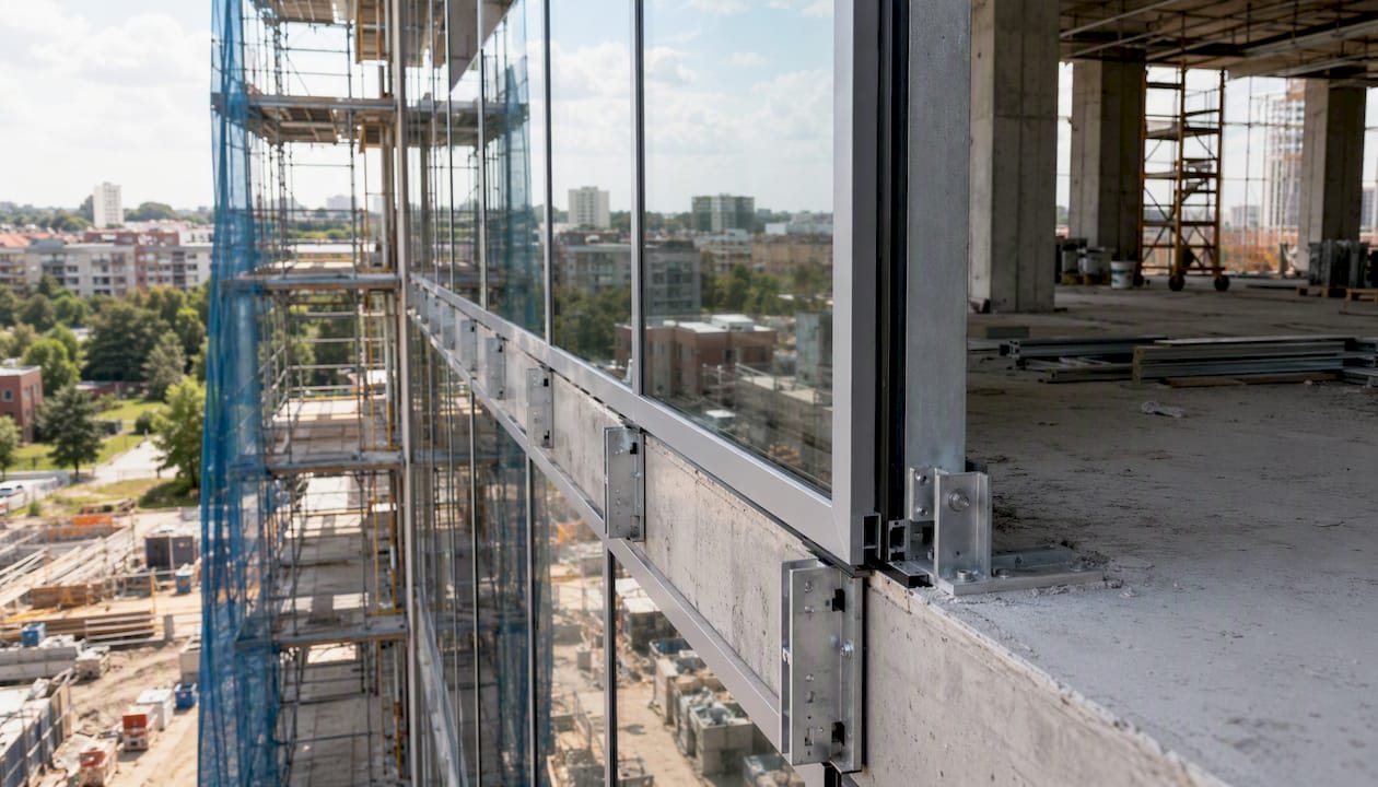
Window wall systems differ in one critical way: they are slab-supported rather than hung from the structure. Each unit bears on the slab below and is laterally restrained by the slab above, which means differential slab deflection and inter-story drift must be accommodated in the anchor design. Window walls are common in mid-rise residential and mixed-use projects where the cost of a full curtain wall system is not justified.
Both systems rely on pressure-equalized rainscreen logic: an exterior glazing or panel layer, a drained and vented cavity, and an inner air/water control layer. The pressure-equalization chamber eliminates the driving force for water infiltration at joints.
Rainscreen and ventilated cladding systems
A rainscreen assembly places an exterior cladding layer outboard of a drainage cavity, which is backed by a WRB applied to the structural sheathing or backup wall. The cavity drains bulk water downward and allows the assembly to dry. GreenGirt composite continuous girts are one example of the subframing systems used to support cladding and maintain the drainage gap while also providing a thermal break between the cladding and the backup structure.
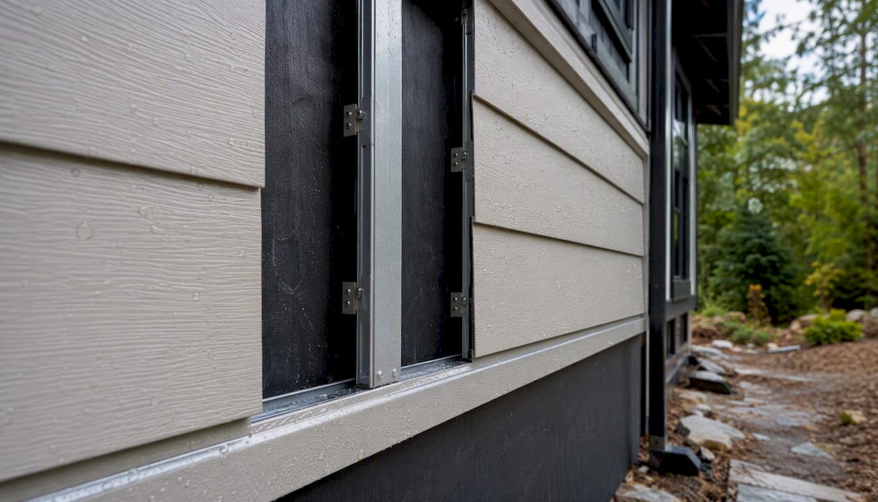
Rainscreen systems perform well in high-moisture climates (IECC Climate Zones 4 through 7) because they do not rely on perfect sealing at the cladding joints. Building Science resources recommend this managed moisture approach, accepting that some wetting will occur and designing for drainage and drying rather than a perfect barrier. Cladding materials include fiber cement, metal panels, terracotta, stone, and high-pressure laminate.
Mass and monolithic walls
Cast-in-place concrete, CMU, and brick masonry rely on the mass of the wall itself to resist bulk water and moderate temperature swings. Moisture management depends on coatings, sealants, and through-wall flashing rather than a drainage cavity. Thermal performance is typically lower than cavity-based systems unless exterior continuous insulation is added outboard of the mass wall. Mass walls are most effective in climates with large diurnal temperature swings, where thermal mass delays peak heat gain.
Insulated concrete forms (ICFs)
ICFs use stay-in-place expanded polystyrene (EPS) forms that are filled with reinforced concrete. The insulation is integral to the form, providing continuous insulation on both faces of the concrete core. Fox Blocks ICFs, for example, are specified for low-to-mid-rise residential and light commercial projects where high airtightness and continuous insulation are priorities. The concrete core provides structural capacity, thermal mass, and a substrate for interior and exterior finishes. Air barrier continuity requires careful attention at window and door rough openings and at the roof-to-wall transition.
EIFS and composite cladding systems
EIFS applies a polymer-modified base coat and finish coat over continuous EPS or mineral wool insulation boards adhered or mechanically fastened to a substrate. The continuous exterior insulation is a thermal performance advantage, but EIFS has a documented history of moisture problems when drainage is not incorporated. Modern EIFS specifications require a drainage plane behind the insulation board and a WRB on the substrate. NFPA 285 fire testing is required when EIFS is used on buildings over 40 feet in height with combustible components.
Masonry veneer, CMU, and precast panels
Brick veneer over a steel stud or CMU backup wall is among the most common mid-rise assemblies in US practice. The cavity between the veneer and the backup wall must be drained through weep holes at the base and at through-wall flashing locations. IKO manufactures WRB and air-barrier membranes that are commonly installed on the backup wall face before veneer installation. The air barrier in this assembly typically sits at the backup wall, and continuous insulation can be placed in the cavity or outboard of the backup.
Precast concrete panels are factory-produced and arrive on site with reinforcement, connections, and often integral insulation. Tilt-up panels are cast on the slab and tilted into place, making them cost-effective for single-story industrial and warehouse buildings. Both systems require careful joint design: sealant joints between panels are the primary water and air control points, and they require a defined maintenance and resealing cycle.
Prefabricated panel systems
Prefabricated panels integrate multiple control layers in a factory-controlled environment, then arrive on site ready to connect. Systems range from structural insulated panels (SIPs) for low-rise construction to engineered metal composite panels for mid-to-high-rise applications. The schedule advantage is significant: factory production runs in parallel with site work, compressing the construction timeline. Control-layer continuity at panel-to-panel joints and at the interface with the roof and foundation requires detailed connection design.
Double-skin façades
A double-skin façade places two glazed layers with an intermediate buffer zone, typically 200–1,500 mm wide, between them. The buffer zone moderates temperature extremes, reduces solar gain, and provides acoustic attenuation. Maintenance access to the cavity is a design requirement that adds complexity and cost. Double-skin façades are most common in high-rise commercial and institutional buildings where energy performance and acoustic performance justify the capital investment.
Green walls and vegetated façades
Green walls add a planted layer to the exterior of a building, either as a modular panel system attached to the structure or as a trellis-supported climbing plant system. The primary envelope assembly behind the green wall must be fully weathertight and independently functional. The planted layer provides supplemental shading and evaporative cooling benefits, but it also retains moisture against the cladding if the drainage design is inadequate.
Pro Tip: For rainscreen assemblies, specify the minimum cavity depth in the contract documents (typically 3/4 inch to 1 inch clear) and require the contractor to verify cavity continuity during installation. Compressed or blocked cavities defeat the drainage and drying function.
How do envelope systems compare on thermal, moisture, fire, and cost performance?
Performance trade-offs drive system selection as much as aesthetics or structural logic. The dimensions that matter most to a specifier are thermal performance, moisture management strategy, airtightness, constructability, durability, and fire code compliance.
Thermal performance and continuous insulation
ASHRAE 90.1 and the IECC set minimum continuous insulation (ci) requirements for opaque assemblies that vary by climate zone and construction type. Cavity insulation alone does not satisfy ci requirements because structural framing members create thermal bridges that reduce the effective R-value of the assembly. Exterior continuous insulation, placed outboard of the structure, eliminates the framing thermal bridge and is the most reliable way to meet code-required assembly U-factors.
The Building Envelope Design Guide (WBDG) notes that high-performance envelopes combining extreme airtightness with continuous insulation enable mechanical system downsizing and lifecycle cost benefits that offset higher initial enclosure costs. An Energy confirms that the enclosure is a primary determinant of energy demand, and that improving thermal performance and airtightness together allows HVAC equipment to be sized smaller.
Moisture management: drained vs. barrier strategies
Building Science resources are explicit: all assemblies will experience wetting, and designs that rely on a perfect barrier are higher risk than those that incorporate drainage and drying capacity. Rainscreen systems with a vented drainage cavity are the most forgiving moisture management strategy. Barrier-based systems (face-sealed EIFS, sealant-dependent precast joints) require more rigorous maintenance and resealing to maintain performance over time.
Airtightness
The air barrier’s location within the assembly affects both energy performance and moisture risk. An air barrier placed at the exterior face of the sheathing (outboard of the structure) keeps the structural framing in the conditioned zone, reducing condensation risk. An interior air barrier (vapor-barrier-as-air-barrier) is common in residential construction but requires careful detailing at penetrations. ASHRAE 90.1 requires whole-building air leakage testing for certain building types, and the threshold is typically 0.40 cfm/ft² at 75 Pa for commercial buildings.
Constructability and schedule
Prefabricated and unitized systems compress the construction schedule by moving work off the critical path and into a factory. The trade-off is lead time: unitized curtain wall panels and prefabricated assemblies require early design freeze and long procurement windows. Site-built rainscreen and masonry veneer systems offer more design flexibility late in the process but require more site labor and weather-dependent installation windows. Value engineering analysis of envelope systems should account for lifecycle costs, not just first cost.
Durability and maintenance
Sealant joints in precast and tilt-up systems typically require inspection every 10 years and resealing every 20–25 years, depending on sealant type and UV exposure. Glazing systems require periodic inspection of gaskets and sealants. Masonry veneer is durable but requires repointing of mortar joints over a 50–75 year service life. Metal panel rainscreen systems can achieve 40+ year service lives with minimal maintenance if the drainage cavity remains clear.
Fire performance and NFPA 285
NFPA 285 is the standard fire test method for evaluating the fire propagation characteristics of exterior non-load-bearing wall assemblies that contain combustible components. It applies to EIFS, rainscreen assemblies with combustible cladding or insulation, and other systems where combustible materials are present in the wall assembly on buildings over 40 feet in height. Compliance with NFPA 285 must be verified through tested assemblies, not by component substitution. Closed-cell spray polyurethane foam, per the AIA/MBA Joint Committee building envelope document, introduces combustible-cladding concerns that require NFPA 285 evaluation when used as a continuous exterior layer.
Pro Tip: When specifying tested performance thresholds, reference the specific ASTM test method and the acceptance criterion in the same spec clause. For example: “Air leakage shall not exceed 0.06 cfm/ft² when tested per ASTM E283 at 1.57 psf (75 Pa) differential pressure.” Vague performance language produces vague submittals.
Pro Tip: Require jobsite verification through field water spray testing per ASTM E1105 at representative window and wall locations before enclosure is complete. Field conditions routinely differ from laboratory mock-up conditions.
Statistic callout: The Building Envelope Design Guide (WBDG) and energy.gov guidance both confirm that high-performance envelopes with continuous insulation and verified airtightness allow HVAC systems to be sized smaller, reducing both capital equipment cost and long-term energy expenditure.
What detailing priorities guard against envelope failure at junctions?
Most envelope failures occur at three-dimensional junctions where multiple materials and control layers intersect, not in the field of the wall. The Building Envelope Design Guide (WBDG) identifies slab edges, balconies, parapets, and window perimeters as the highest-risk locations in any assembly.
The University of Michigan building envelope design guidance requires detailed drawings for all envelope penetrations, continuous air-barrier documentation, and independent inspection and testing during construction. These are not optional quality measures; they are the minimum standard for projects involving envelope work.
Required details and documentation checklist:
- Slab edge and floor-to-wall transition: Continuous insulation must wrap the slab edge to prevent thermal bridging; the air barrier must transition from the wall assembly to the roof or floor assembly without gaps.
- Parapet: The air and water control layers must extend up and over the parapet and connect to the roofing membrane; parapet cap flashings must be lapped and sealed.
- Balcony and canopy connections: Structural penetrations through the thermal and air control layers require thermal breaks and careful air-barrier detailing at the penetration perimeter.
- Window and door perimeters: The WRB must be lapped onto the window frame or sill pan flashing; the air barrier must be sealed to the window frame with a compatible sealant or membrane.
- Through-wall flashings: Required at all shelf angles, lintels, and base-of-wall conditions in masonry veneer; must be sloped to drain and terminate with end dams.
- Pressure-equalization openings in rainscreens: Vent openings at the top and bottom of the drainage cavity must be sized and protected against insect infiltration.
- Penetrations (pipes, conduit, structural connections): Each penetration requires a sleeve, a flashing collar, and a sealant connection to the air and water control layers.
Fenestration-specific requirements:
- Specify tested performance per ASTM E283 (air leakage), ASTM E331 (water penetration under static pressure), and ASTM E547 (water penetration under cyclic pressure) for windows and curtain wall.
- Require sill pan flashing with end dams and a positive slope to drain; do not rely on sealant alone at the sill.
- Specify movement allowances at head and jamb to accommodate structural deflection and thermal expansion.
- Condensation resistance factor (CRF) should be specified for glazing systems in cold climates to prevent interior condensation on frames.
Below-grade requirements:
- Waterproofing (not dampproofing) is required at below-grade walls subject to hydrostatic pressure; dampproofing is appropriate only for walls in well-drained soils with no hydrostatic head.
- Under-slab vapor barriers (minimum 10-mil polyethylene per ACI 302) prevent ground moisture from migrating through the slab into the conditioned space.
- Coordinate waterproofing termination with the above-grade WRB to maintain continuity of the water control layer at grade.
Pro Tip: Schedule a cross-disciplinary envelope design review at the end of schematic design, before design development begins. Bring the architect, structural engineer, mechanical engineer, and envelope consultant to the same table with a set of 3D junction sketches. Resolving control-layer conflicts at this stage costs a fraction of what they cost in the field.
Which US codes and standards govern building envelope compliance?
Compliance with US building envelope requirements draws from several overlapping code and standards frameworks. Energy.gov explains that ASHRAE and IECC-based energy-code provisions are developed at the national level and then adopted or amended locally, which means project-level compliance requirements depend on the jurisdiction’s adopted code cycle.
Core standards and codes:
- ASHRAE 90.1: The primary commercial building energy standard; sets minimum assembly U-factors, continuous insulation R-values, fenestration performance, and whole-building air leakage requirements by climate zone. Most states reference ASHRAE 90.1 for commercial construction.
- IECC (International Energy Conservation Code): The residential and commercial energy code adopted by most jurisdictions; updated on a three-year cycle. Provisions align closely with ASHRAE 90.1 for commercial buildings.
- NFPA 285: The fire test standard for exterior wall assemblies containing combustible components; required for EIFS, combustible rainscreen claddings, and combustible insulation on buildings over 40 feet. Compliance is assembly-specific, not component-specific.
- ASTM test methods: ASTM E2947 and related standards cover air leakage (ASTM E283), water penetration under static pressure (ASTM E331), water penetration under cyclic pressure (ASTM E547), and whole-building air leakage (ASTM E779, ASTM E1827). These are the appropriate mechanisms to specify and verify fenestration and cladding performance.
- ISO 81766: The ISO standard for building envelope design principles covers thermal performance, airtightness, watertightness, daylighting, and sustainability for new and retrofit projects; useful as an international best-practice reference alongside US codes.
Building enclosure commissioning (BECx):
Enclosure commissioning connects design intent to field execution. It is recommended on any project where envelope performance is critical to energy targets, occupant comfort, or moisture risk management. BECx typically includes:
- Review of envelope design documents and specifications for control-layer continuity.
- Pre-installation meetings with envelope subcontractors.
- Mock-up construction and testing (water spray, air leakage) before full installation begins.
- Periodic field observations during installation.
- Post-installation testing: blower door (whole-building air leakage), field water spray testing per ASTM E1105, and infrared thermography to identify thermal bridging and moisture intrusion.
Pro Tip: Require a pre-installation meeting for each envelope subcontractor (glazing, roofing, waterproofing, cladding) as a contract requirement, not a courtesy. Use the meeting to review the shop drawings, the mock-up acceptance criteria, and the field testing protocol before any material is installed.
Statistic callout: Building code compliance requirements for envelope performance vary by jurisdiction because states and localities adopt ASHRAE 90.1 and IECC provisions on different cycles and with local amendments. Confirming the adopted code edition and any local amendments is the first compliance step on every project.
What does current research say about continuous insulation and thermal bridging?
The shift from component-based to system-based envelope evaluation is the most consequential change in US envelope practice over the past two decades. Practitioners who specify insulation R-values without accounting for thermal bridging through framing members routinely overestimate the effective thermal performance of their assemblies by a significant margin.
The Building Envelope Design Guide (WBDG) and building science practitioners consistently recommend evaluating the whole-wall R-value, not the nominal cavity R-value. A steel stud wall with R-19 batt insulation between studs at 16 inches on center has an effective whole-wall R-value substantially lower than R-19 because steel is a highly conductive thermal bridge. Adding continuous exterior insulation outboard of the studs is the most effective mitigation strategy.
Practical thermal-bridge mitigation strategies include:
- Exterior continuous insulation (mineral wool or EPS boards) over the full face of the backup wall, with mechanical fasteners or adhesive attachment.
- Thermal breaks at slab edges: a layer of high-compressive-strength insulation (e.g., Rockwool or Foamglas) between the slab edge and the exterior cladding support.
- Composite wall strategies: combining a mass wall with outboard insulation to keep the thermal mass in the conditioned zone.
- Thermally broken framing systems for curtain wall and window wall, where the aluminum frame is interrupted by a polyamide or polyurethane thermal break.
Case example: A mid-rise office building in Climate Zone 5 that improved its opaque wall assembly from a nominal R-13 cavity-only system to an R-13 cavity plus R-10 continuous exterior insulation assembly, combined with verified whole-building air leakage below 0.25 cfm/ft² at 75 Pa, was able to reduce the design heating load sufficiently to downsize the air handling units. The envelope improvement paid for itself through reduced mechanical equipment cost before accounting for energy savings over the building’s service life.
Building Science resources reinforce this finding: the managed moisture approach, combined with continuous insulation and verified airtightness, produces assemblies that are more durable and more energy-efficient than barrier-only or cavity-only strategies. The energy performance implications of the building envelope are well-documented in both US and international practice.
Pro Tip: Commission a whole-wall thermal analysis (using THERM or equivalent finite-element software) for each opaque assembly type on the project before finalizing the insulation specification. The analysis takes a few hours and routinely reveals thermal bridging that would otherwise go undetected until the building fails to meet its energy target.
Statistic callout: Energy.gov guidance confirms that a whole-house systems approach, where the enclosure is treated as the primary energy-demand driver, enables HVAC downsizing and lifecycle cost benefits that offset higher initial enclosure investment.
Representative assemblies and expected performance by project type
The following assemblies represent common US practice across building types. Each is described by its control-layer strategy, moisture approach, and typical service life.
Pro Tip: For any assembly that includes a new material combination or an unusual junction, require a full-scale mock-up and subject it to both water spray testing (ASTM E1105) and air leakage testing before approving the system for installation. Mock-up failures are far less expensive than field failures.
| Assembly | Best-for | Thermal (U-factor / R-value guidance) | Moisture approach | Typical maintenance interval |
|---|---|---|---|---|
| Unitized aluminum curtain wall with pressure-equalized rainscreen | High-rise commercial, institutional | U-0.38 or better (ASHRAE 90.1 CZ4); thermally broken frame | Pressure-equalized drainage; inner air/water layer | Gasket inspection every 10 yr; sealant every 20–25 yr |
| Mid-rise brick veneer over steel stud with ci (e.g., IKO WRB + mineral wool ci) | Mid-rise residential, mixed-use | Assembly U-factor meeting ASHRAE 90.1 requirements for the climate zone | Cavity drainage; through-wall flashing; WRB at backup | Repoint mortar at 50–75 yr; inspect weeps every 10 yr |
| Low-rise precast insulated sandwich panel with sealed joints | Industrial, warehouse, mid-rise | R-value integral to panel (varies depending on foam core thickness and type) | Sealed joints; barrier-based; no drainage cavity | Reseal joints every 20–25 yr; inspect connections every 10 yr |
| ICF wall (e.g., Fox Blocks) with exterior finish | Low-to-mid-rise residential | R-22 to R-26 effective (EPS both faces + concrete) | Coatings and sealants at exterior; no drainage cavity | Inspect and reseal penetrations every 10 yr |
| EIFS with drainage plane over CMU backup | Commercial, mid-rise | ci R-10 to R-20 outboard; low thermal bridging | WRB at CMU face; drainage plane behind EPS | Inspect finish coat every 10 yr; reseal at 20–25 yr |
| Rainscreen with metal panel cladding over GreenGirt composite girts | Any height, high-moisture climates | ci outboard of backup wall; girts provide thermal break | Drainage cavity; WRB at backup | Inspect cavity drainage at 5 yr; panel fasteners at 10 yr |
Shop drawing and mock-up coordination notes:
- Require shop drawings for all glazing systems, curtain wall, and prefabricated panel systems that show the air-barrier connection at head, sill, and jamb conditions.
- Mock-up triggers: any new assembly type, any assembly with a combustible component requiring NFPA 285 compliance, and any project where the envelope area exceeds a threshold defined in the project specifications.
- Coordinate shop drawings between the glazing contractor, the WRB installer, and the cladding contractor before any installation begins. Sequencing conflicts between these trades are a leading cause of air-barrier discontinuities.
How do you select and specify the right envelope system?
System selection follows a priority order. Climate and moisture risk drive the first decision; structural interface and energy-code targets refine it; maintenance budget and constructability close it.
Selection checklist (priority order):
- Program and durability requirements: What is the design service life? What occupancy and use conditions drive the performance specification?
- Climate and moisture risk: What is the IECC climate zone? Is the site exposed to wind-driven rain, freeze-thaw cycling, or high humidity? High-moisture climates favor drained and ventilated assemblies.
- Building height and structural interface: Does the building height require a non-load-bearing curtain wall, or is a slab-supported window wall or load-bearing panel system appropriate? What are the inter-story drift and slab deflection limits?
- Energy-code targets: What are the ASHRAE 90.1 or IECC minimum assembly U-factors and ci requirements for the climate zone and construction type? Does the project pursue a stretch code or green building certification that requires performance above the minimum?
- Maintenance budget: What is the owner’s long-term maintenance commitment? Sealant-dependent systems require a defined resealing program; drainage-based systems are more forgiving.
- Constructability and schedule: Is the project schedule compatible with the lead times for unitized or prefabricated systems? Is the site accessible for large panel delivery and crane erection?
Decision flow:
- Climate-first (moisture risk) → control-layer strategy (drained vs. barrier) → material and system family → mock-up and testing requirements.
Sample specification clause starters:
- Air-barrier continuity: “The air barrier system shall be continuous across all envelope assemblies, including transitions between wall and roof, wall and foundation, and at all penetrations. Continuity shall be documented on the air-barrier continuity plan drawing and verified by the envelope commissioning agent during construction.”
- Mock-up acceptance: “A full-scale mock-up of each opaque wall assembly type shall be constructed and tested per ASTM E1105 (water penetration) and ASTM E283 (air leakage) before installation of the system in the field. The mock-up shall include at least one window or door opening and one horizontal-to-vertical transition.”
- Performance threshold: “Fenestration assemblies shall have a tested air leakage rate not exceeding 0.06 cfm/ft² at 1.57 psf (75 Pa) differential pressure when tested per ASTM E283. Water penetration shall not occur at a test pressure of [specify project-specific value] psf when tested per ASTM E331.”
- Thermal performance: “Opaque wall assemblies shall achieve a maximum whole-assembly U-factor of [specify per ASHRAE 90.1 climate zone] as calculated using THERM or equivalent finite-element thermal analysis software, accounting for all framing members and mechanical fasteners that penetrate the continuous insulation layer.”
A practitioner’s perspective on system-based envelope design
The most persistent gap in building envelope practice is not a lack of good products or good standards. It is the gap between what the drawings show and what gets built. Envelope failures cluster at junctions, penetrations, and transitions, precisely the locations where the design team assumed coordination would happen without explicitly requiring it.
System-based envelope design closes that gap by treating the control layers as a continuous, coordinated system rather than a collection of independently specified components. When the air-barrier continuity plan is a contract document, when the mock-up acceptance criteria are in the specification, and when the enclosure commissioning agent has authority to hold installation until field testing passes, the probability of a significant envelope failure drops substantially.
For complex projects, particularly those with combustible cladding assemblies subject to NFPA 285, high-moisture climate exposures, or aggressive energy targets, enclosure commissioning is not an optional add-on. It is the mechanism that connects design intent to field execution. Aectechnicalsg’s technical advisory services support design teams through the full envelope specification and commissioning process, from control-layer strategy through mock-up testing and field verification.
Use the selection checklist in the preceding section as a starting point for every project. Require mock-ups for any assembly type that is new to the project team or that contains combustible components. And schedule the cross-disciplinary envelope review before design development begins, not after the construction documents are 90 percent complete.
For projects requiring authority submissions and technical endorsements, Aectechnicalsg provides qualified engineering support from envelope specification through regulatory compliance.
Sources
The following references provide the code language, test methods, and design guidance cited throughout this article.
- Building Envelope Design Guide (WBDG)
- University of Michigan building envelope design guidance
- AIA/MBA Joint Committee building envelope document
- ASTM E2947 and related test-method standards
Recommended
- Computational Fluid Dynamics (CFD)
- Advanced Concrete Formwork Systems: Guide to Quality & Efficiency (2025)
- SS EN 1992-1-1:2024: Singapore PE’s Guide to Eurocode 2
- Taming the Tropical Gale: Wind Engineering, Façade Design, and Occupant Comfort in Singapore’s High-Rise Buildings – AEC Technical Advisory Singapore Engineering Consultancy