
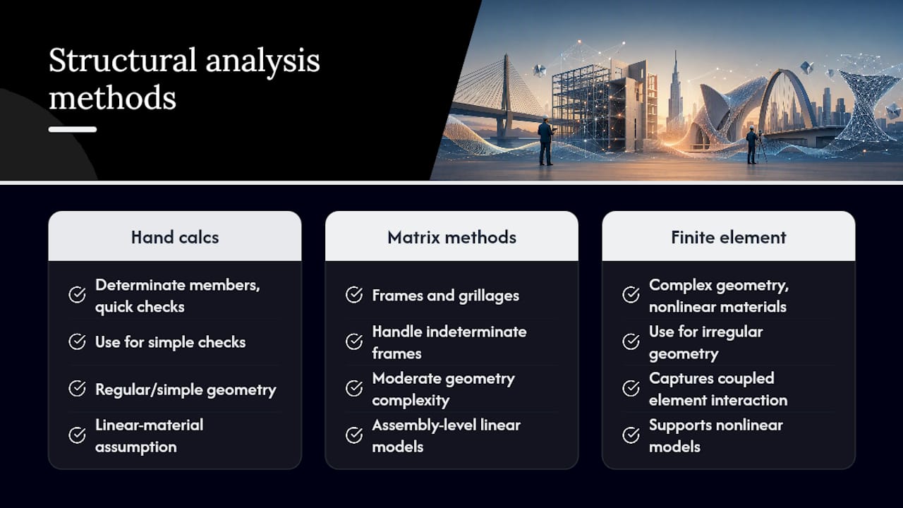
Structural analysis methods fall into three families: hand calculations built on mechanics of materials, elasticity and matrix methods, and finite-element methods (FEM). Hand calculations handle determinate members and quick checks. Elasticity and matrix approaches solve continuum problems and frame systems where closed-form or semi-analytic solutions still apply. FEM covers everything else: irregular geometry, mixed materials, nonlinear behavior.
The selection rule that governs all three, per AISC guidance on steel truss bridge analysis, is simple: pick the least complex method that still delivers the accuracy and results the question demands, then cross-check the output against a simpler model or a hand calculation.
- Hand calculations: determinate beams, trusses, sanity checks on larger models
- Elasticity/matrix methods: frames, grillages, plates where a semi-analytic solution holds
- FEM: complex geometry, nonlinear materials, coupled load paths, anything a spreadsheet can’t touch honestly
Key Takeaways
Structural analysis works best when engineers match method complexity to the engineering question and verify every model against a simpler check.
| Point | Details |
|---|---|
| Match method to question | Use hand calculations, matrix methods, or FEM based on required accuracy, not habit. |
| Enforce the three principles | Equilibrium, compatibility, and constitutive relations apply regardless of tool. |
| Check nonlinearity triggers | Slenderness, inelastic demand, and large deformations signal when linear analysis falls short. |
| Pair NDT with analysis | Field data from UPV, GPR, or strain gauges should validate, not replace, model assumptions. |
| Validate every FEM model | Run mesh convergence, boundary checks, and hand-calc comparisons before trusting results. |
Table of Contents
- What Is Structural Analysis and What Is It Trying to Achieve?
- Hand Calculations, Elasticity Methods, and FEM Compared
- Linear Versus Nonlinear Analysis: What Changes and Why
- Static Versus Dynamic Analysis: Modal, Response-Spectrum, and Time-History Methods
- Stability and Buckling Analysis: Approaches and a Practical Checklist
- Structural Optimization: Objectives and Common Techniques
- Structural Health Monitoring and NDT as Analysis Inputs
- How to Choose a Method and Validate an FEM Model
- Software Categories and a Typical Modeling Workflow
- Frequently Asked Questions
- Sources
What Is Structural Analysis and What Is It Trying to Achieve?
Structural analysis determines the internal forces, reactions, and displacements a structure experiences under load, then measures those results against failure and serviceability limits. That is the whole job. Every method, from a two-minute moment calculation to a 500,000-element shell model, exists to answer that same question at a different level of resolution.
Three principles govern the exercise regardless of tool, according to MIT’s Introduction to Structural Analysis course:
- Equilibrium — forces and moments balance at every point and joint
- Compatibility — deformations remain geometrically consistent across connected members
- Constitutive relations — the material’s stress-strain behavior is modeled accurately
The outputs, reactions, stress, and displacement, feed directly into design checks referenced against AISC steel provisions, AASHTO bridge specifications, or ACI concrete standards. A method that skips any of the three principles produces numbers, not answers.
Hand Calculations, Elasticity Methods, and FEM Compared
Structural analysis techniques are typically grouped into these three categories, and the boundaries between them matter more than most students realize once real project geometry gets involved, per the Wikipedia overview of structural analysis.
Hand calculations / mechanics of materials solve determinate beams, simple trusses, and standard cross-sections using closed-form formulas. They are fast and fully transparent: every assumption sits in plain sight on the page. Their limitation shows up the moment a system becomes indeterminate, three-dimensional, or geometrically irregular. A simply supported beam formula tells you nothing about torsional warping in an open channel section.
Elasticity and matrix methods step up to continuum problems and framed systems. Matrix stiffness methods, the natural bridge between classical mechanics and FEM, handle frames and grillages efficiently and remain a staple for building frame analysis, according to MIT’s course on structural analysis techniques. Analytic elasticity solutions still solve certain plate and shell problems without a mesh.
Finite-element methods generalize to arbitrary geometry, mixed materials, and nonlinear response. That flexibility is also the risk: a fine mesh with a bad boundary assumption produces confident, wrong answers. Mesh sensitivity and support idealization are the two failure points that catch even experienced modelers.
| Method family | Best for | Main limitation |
|---|---|---|
| Hand calculations | Determinate beams, trusses, quick checks | Breaks down on indeterminate or 3-D systems |
| Elasticity/matrix | Frames, grillages, plate/shell problems with regular geometry | Limited to conditions where semi-analytic solutions exist |
| FEM | Complex geometry, nonlinear materials, coupled behavior | Mesh sensitivity, boundary-condition risk, verification burden |
Real projects rarely use one method in isolation. A common workflow, per Turn2Engineering’s structural analysis overview, runs matrix stiffness for the overall frame, then drops to FEM for a slab punching-shear check or a connection detail where stress concentrations matter.
Linear Versus Nonlinear Analysis: What Changes and Why
Linear analysis assumes small strains, a linear stress-strain relationship, and superposition, meaning you can add the effects of separate load cases together. It works well for service-load checks on stable, lightly stressed structures, and it’s the default for most preliminary design.
Nonlinear analysis becomes necessary once any of these show up:
- Material nonlinearity — steel yielding, concrete cracking, or any post-elastic behavior
- Geometric nonlinearity — large deformations, P-Delta effects in tall or slender frames
- Contact and interface behavior — bearing surfaces, gaps, friction-dependent connections
Decide based on slenderness ratio, how close the structure sits to a buckling threshold, and whether the design intentionally permits inelastic demand (as in seismic design). If a column’s axial load approaches its critical buckling load, or a frame’s lateral drift triggers P-Delta amplification, linear analysis will understate demand. The added modeling cost of nonlinear analysis only pays off when linear results leave real doubt about behavior near a limit state.
Static Versus Dynamic Analysis: Modal, Response-Spectrum, and Time-History Methods
Static analysis assumes loads apply slowly enough that inertia doesn’t matter. Dynamic analysis accounts for time-dependent loading and the inertial forces that come with it, and it’s mandatory once vibration, seismic demand, or moving machinery enters the picture.
Three dynamic approaches cover most practical cases:
- Modal (eigenvalue) analysis — finds natural periods and mode shapes, the foundation for any dynamic study
- Response-spectrum analysis — combines modal results with a code-defined spectrum, standard practice for seismic design
- Time-history analysis — runs an actual load record through the model, used for critical structures or unusual dynamic sources like pedestrian-induced footbridge vibration
Get mass and damping assignments right before trusting any dynamic output.
Stability and Buckling Analysis: Approaches and a Practical Checklist
Buckling failures happen suddenly and often at loads well below the material’s yield strength, which is exactly why they demand a distinct analysis track rather than a footnote in a strength check.
- Run a preliminary slenderness check. Classical Euler buckling with an effective length factor flags members that need closer attention.
- Estimate second-order effects. P-Delta (frame sway) and P-delta (member curvature) amplify moments beyond first-order results; approximate methods catch most cases.
- Escalate to eigenvalue or nonlinear buckling analysis for complex systems where interaction between members, bracing, or torsion makes hand methods unreliable.
- Test sensitivity to imperfections. Real members are never perfectly straight; codes require an assumed out-of-straightness or load eccentricity, and results should be checked against it.
A slender moment-frame column carrying combined axial and lateral load is the textbook trap: it passes a first-order check comfortably, then fails a second-order review because nobody carried the P-Delta amplification through the connection design.
Structural Optimization: Objectives and Common Techniques
Optimization in structural design chases a handful of goals: minimum mass, controlled natural frequencies, and serviceability limits met without excess material. Constraints usually come from code-mandated strength limits and stiffness requirements that can’t be traded away.
Common techniques include:
- Gradient-based optimization for continuous variables like member sizing
- Genetic algorithms for discrete, combinatorial problems (bracing layout, member selection from a catalog)
- Topology optimization within FEM environments, generating organic load-path geometries for weight-critical applications
Pro Tip: Topology optimization can produce a geometry that’s materially efficient but nearly impossible to fabricate or form. Run every optimized result through a constructability review before it reaches drawings, not after.
Structural Health Monitoring and NDT as Analysis Inputs
Structural health monitoring (SHM) and nondestructive testing (NDT) don’t replace analysis, they feed it; knowing when to call a structural engineer during a home inspection can be crucial for accurate assessment. Material properties, boundary conditions, and degradation states all come from field data, and an analysis built on assumed rather than measured inputs is only as good as the assumption.
Common NDT technologies include:
- Ultrasonic pulse velocity (UPV) — estimates concrete quality and detects voids
- Impact-echo — locates delamination and internal flaws
- Acoustic emission — monitors active crack growth under load
- Rebound hammer / penetration resistance — quick surface-level concrete strength estimates
- Ground-penetrating radar (GPR) — maps reinforcement layout and cover depth
- Strain gauges — validate model predictions against real load response
The NIST review of nondestructive evaluation for concrete catalogs these methods in detail, and it flags a real gap: many service-life prediction models weren’t originally calibrated against the specific NDT outputs engineers now feed them. Treat NDT-to-model correlations as informed estimates, not exact inputs, and pair analysis with a physical load test whenever the stakes justify the cost.
How to Choose a Method and Validate an FEM Model
Method selection isn’t a lookup table. AISC’s guidance is explicit that there’s no single prescriptive rule; engineers weigh structure complexity and expected behavior against the refinement a model actually needs.
Selection checklist:
- Define the engineering question precisely (capacity check, deflection limit, dynamic response).
- List the critical outputs the analysis must produce.
- Quantify how much uncertainty is acceptable for this decision.
- Choose the minimal-refinement method that can deliver those outputs within that uncertainty.
- Plan verification steps before the model becomes the basis for design.
FEM validation checklist:
- Sanity-check geometry and boundary conditions against the physical structure.
- Run a mesh convergence study; if results keep shifting as the mesh refines, the model isn’t ready.
- For dynamic models, confirm modal periods and participation mass make physical sense.
- Verify the load path matches the intended structural system, not an artifact of how supports were modeled.
- Compare FEM results against a hand calculation for at least one representative section.
- Run a sensitivity sweep on material properties and support stiffness to see how much the answer moves.
AISC’s B908 module places methods on a spectrum running from simplified classical beam and V-load approaches up to rigorous 2-D grillage and 3-D shell models, and the guidance consistently favors matching refinement to the actual design question rather than defaulting to the most detailed tool available.
Pro Tip: Document every assumption, mesh decision, and sensitivity result as you go. A punching-shear check cross-referenced against a strip-model hand calculation is worth more in a code review than a prettier render of the same slab. For connection-level work, a detailed FEM validation approach for complex steel connections shows how that documentation habit plays out on a real project.
Software Categories and a Typical Modeling Workflow
Tools break into a few practical categories: hand-calc aides (spreadsheets, code-check utilities), frame and matrix-stiffness packages for building frames, general-purpose FEM software for complex geometry, and specialty solvers for soil-structure interaction or dynamic response. Geotechnical-structure coupling, for instance, often calls for a dedicated tool like the kind used in PLAXIS-based impact assessments.
A workable modeling sequence:
- Define the scope and required outputs.
- Simplify geometry to the level the question demands, no further.
- Choose element types (beam, shell, solid) that match the actual behavior.
- Assign materials and sections with sourced, not assumed, properties.
- Apply loads and boundary conditions that reflect real support conditions.
- Run the analysis, then verify against hand calculations or a simpler model before trusting the output.
- Keep hand calculations in the loop at every stage, not just at the start
- Reserve physical load testing for cases where model uncertainty genuinely threatens the decision
For building-scale projects, a structured approach to matching refinement level to project type is covered in Aectechnicalsg’s guide to structural design decisions for developers.
A note from the field
Choosing the simplest method that answers the question, then documenting every assumption behind it, is the single habit that separates a clean code submission from months of rework. It’s not glamorous advice, but it holds up on every project where the analysis actually gets checked.
Frequently Asked Questions
What are the main types of structural analysis methods?
The three primary families are hand calculations (mechanics of materials), elasticity and matrix methods, and finite-element methods. Hand calculations suit determinate members and quick checks; matrix methods handle frames and grillages; FEM covers complex geometry, nonlinear materials, and coupled behavior.
When should I use FEM instead of hand calculations?
Use FEM when geometry is irregular, materials behave nonlinearly, or load paths involve interaction between elements that a closed-form formula can’t capture. Cross-check FEM results against a hand calculation for at least one representative section before trusting the model.
What’s the difference between static and dynamic structural analysis?
Static analysis assumes loads apply slowly enough that inertia is negligible. Dynamic analysis accounts for time-dependent loads and inertial effects, using modal, response-spectrum, or time-history methods depending on the source of dynamic demand.
How do NDT methods relate to structural analysis?
NDT methods like ultrasonic pulse velocity, impact-echo, and ground-penetrating radar supply real material and condition data that feed analysis models, particularly for existing structures where drawings are incomplete or degradation has occurred.
Do I need nonlinear analysis for every project?
No. Linear analysis remains appropriate for most service-load checks on stable structures. Nonlinear analysis becomes necessary when material yielding, large deformations, or proximity to buckling thresholds threaten to invalidate the small-strain, linear assumption.
Sources
For method selection, start with AISC’s B908 structural analysis module and its steel truss bridge guidelines. For NDT implementation, use the NIST review of concrete evaluation methods. For existing-structure assessment combining analysis with load tests, consult ACI’s guidance on evaluating existing buildings. For theoretical fundamentals, MIT OpenCourseWare’s structural analysis lecture series remains the clearest starting point.
Projects that need refined analysis carried through to authority submission benefit from consultancy support at the modeling stage itself. Aectechnicalsg’s engineering consultancy services for Singapore developers cover structural analysis, FEM validation, and the authority-submission packages that depend on getting that analysis right the first time.
- Guidelines for steel truss bridge analysis — AISC
- MIT OCW — Introduction to Structural Analysis (Lecture 3)
- NIST IR 7974 — Nondestructive evaluation for concrete structures