
Introduction
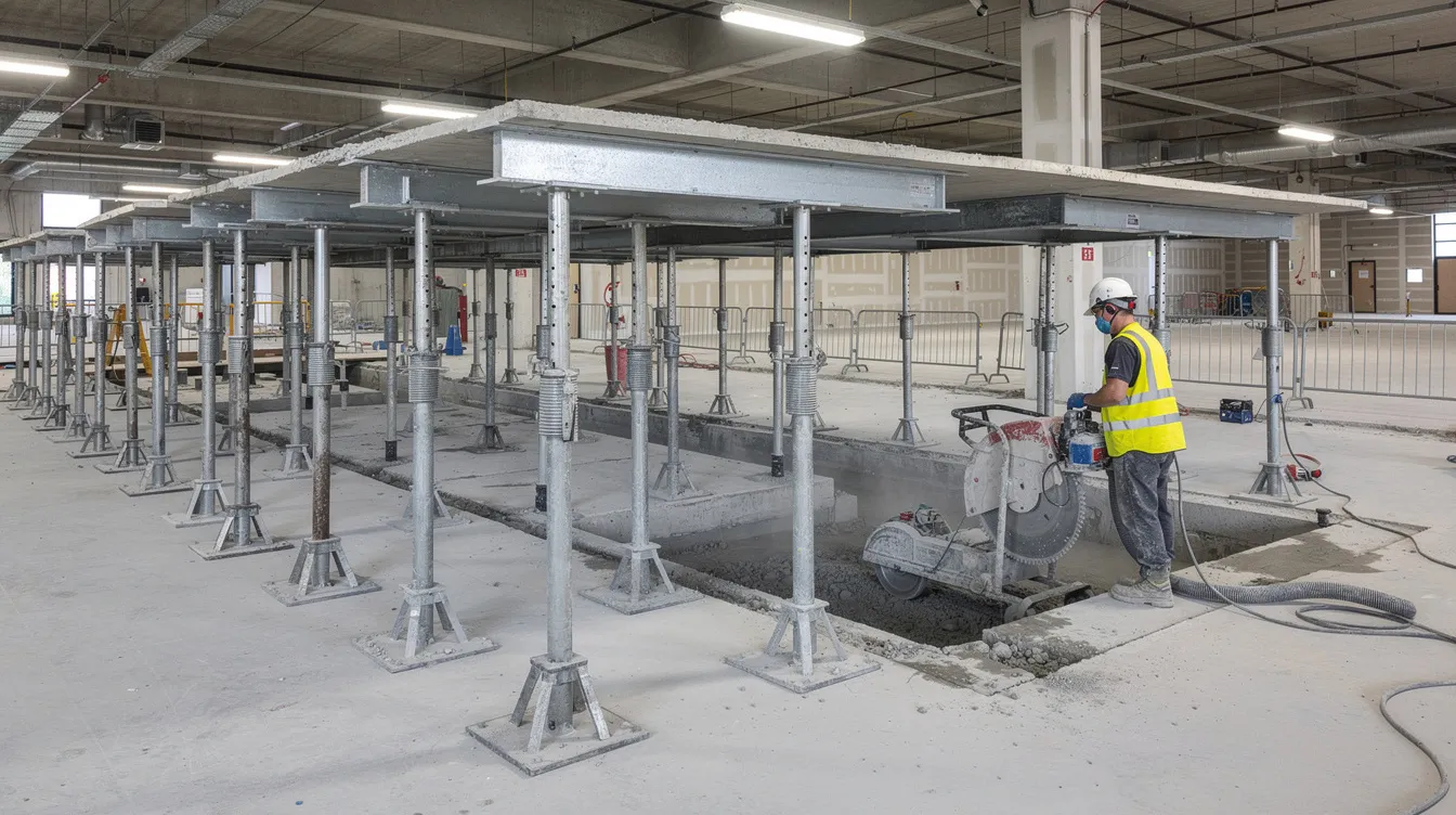
Cutting an opening through a structural slab – whether for a new staircase, service duct, or mechanical shaft – permanently disrupts the load paths that keep a building standing. Temporary propping for internal slab cutting is part of shoring in construction, serving as the engineered temporary support system that maintains structural integrity during this transition, transferring vertical loads safely through the existing structure until permanent reinforcement is in place.
This comprehensive guide covers the full scope of temporary load transfer during the creation of internal openings in Singapore construction projects. It addresses the engineering principles behind propping systems, the regulatory framework governing these regulated structural modification works within civil engineering practice under the Building Control Act, and the practical installation methodology that keeps sites safe. Topics outside this scope – such as deep excavations, retaining walls, or facade retention – are referenced only where they inform the core discussion. The target audience is contractors, property owners, and project managers undertaking addition and alteration (A&A) works who need to understand why these systems matter and what the law requires.
The direct answer: PE structural calculations are mandatory under Singapore building regulations for any temporary works affecting structural elements. Before a single cut is made in a structural slab, a Professional Engineer must design, calculate, and endorse the temporary propping arrangement to ensure safe load redistribution throughout the cutting and reinforcement sequence.
By the end of this article, you will understand:
-
How load paths change when internal openings are introduced in structural slabs
-
What Singapore’s regulatory framework requires for temporary works design and PE endorsement
-
How propping systems are selected, calculated, and installed for internal slab cutting
-
The common challenges encountered during these operations and their engineering solutions
-
The monitoring and safety protocols that prevent structural failure during works
Understanding Temporary Load Transfer in Structural Modification
Temporary load transfer is the controlled redirection of forces – dead loads, live loads, and imposed loads – from a structural element that is about to be altered to adjacent load bearing elements that can safely absorb those forces. In the context of internal slab cutting, this means ensuring that the weight previously carried by the section of slab being removed continues to travel through a continuous path to the foundation, via temporary propping systems, until permanent structural modifications restore the designed load bearing capacity.
When a section of slab is removed, the structural continuity of reinforcement is broken. The slab can no longer span as originally designed. Bending moments increase at the edges of the new opening, shear forces concentrate around the perimeter, and support reactions at adjacent beams and columns shift. Without a properly designed temporary support system, these redistributed forces can overstress elements that were never designed to carry them, risking collapse or irreversible damage to the existing structure.
Load Path Analysis for Internal Openings
In a typical reinforced concrete building, loads travel through a predictable sequence: from the slab surface, through the slab’s reinforcement and concrete, into supporting beams, down through columns, and finally into the foundation. This is the load path – the route every kilonewton of force follows from point of application to the ground.
Creating an opening in a slab disrupts this path fundamentally. A two-way slab relies on reinforcement running in both directions to distribute loads efficiently. When that reinforcement is cut, the slab’s stiffness drops, deflections increase, and the moment distribution changes in ways the original designer never anticipated. Research published in Structures journal demonstrated that even a 300 mm square opening cut in the mid-span of a two-way slab reduced its load-carrying capacity measurably – and that adding reinforcement around the opening recovered only approximately 15–20% of the lost capacity.
This is precisely why temporary support becomes critical before any permanent reinforcement is installed. Propping systems must intercept the loads that the removed slab section would have carried and redirect them downward through the structure – maintaining a continuous trajectory to the foundation – until new edge beams, trimmer bars, or other permanent strengthening measures are in place and capable of carrying the design loads independently.
Types of Internal Openings Requiring Temporary Propping
Not all openings are equal. The type, size, and location of the opening determine the magnitude of load redistribution and the complexity of the temporary works design required.
Staircase openings in residential and commercial buildings are among the most demanding. They typically require large rectangular cuts – often 2 metres or more in width – that remove significant structural slab area and sever primary reinforcement in both directions. The resulting uneven load distribution requires robust propping with careful attention to edge beam design.
Service duct penetrations for MEP installations tend to be smaller but may occur in clusters, and their cumulative effect on slab stiffness can be significant. Each penetration requires assessment of its impact on the surrounding reinforcement and load paths.
Mechanical shaft openings for lifts and HVAC systems often penetrate multiple floors, meaning that propping strategies must account for load transfer through several storeys simultaneously – making back-propping calculations essential.
Each opening type requires specific propping strategies tailored to its geometry, location relative to beams and columns, and the loads it must redirect. Understanding these distinctions is the foundation for engaging the right engineering support and regulatory approvals.
Singapore Regulatory Framework and PE Requirements
Singapore’s built environment regulations treat temporary works with the same seriousness as permanent structures. The Building Control Act requires that any building works affecting key structural elements – which internal slab cutting unquestionably does – must be submitted, approved, and supervised by qualified professionals. Temporary shoring prevents structural collapse during construction phases, and the regulatory framework exists to ensure this protection is engineered, not improvised.
PE Structural Calculations Under Singapore Building Regulations
Under Singapore law, temporary supports must be designed by qualified structural engineers, and any temporary support arrangement requires formal shoring design. A Professional Engineer registered with the Professional Engineers Board (PEB) must endorse the structural calculations, drawings, and method statements for any temporary propping systems that affect structural integrity.
The PE’s responsibilities include:
-
Calculating all load components (self weight of the slab, finishes, services, live loads, and construction loads) at each stage of the cutting sequence
-
Designing the propping arrangement with safety factors not lower than those used for permanent works
-
Specifying prop types, capacities, spacing, and connection details
-
Preparing the erection and removal sequence to ensure loads are never unsupported
-
Certifying that the temporary works conform to Singapore Standards (SS EN 1992 for reinforced concrete, SS EN 1993 for steel) or equivalent codes
For projects involving critical structural elements, an Accredited Checker (AC) may also be required to independently verify the PE’s design – adding a second layer of assurance. This independent checking requirement, stipulated in LTA’s Engineering Group Document E/GD/09/104/A2, reflects the principle that temporary works must be designed for foreseeable loads and utilize competent engineers.
HDB’s January 2026 circular further reinforces these requirements by mandating that trimming bars – including lapping lengths and bar sizes – must be explicitly shown in plan submissions for any openings such as floor trap penetrations or discharge pipe routes. The circular also prohibits coring through prestressed or hollow-core slabs without prior approval.
Authority Submission Process
The BCA structural plan submission process for slab modifications follows a defined pathway. The Qualified Person (QP) – typically the PE – must prepare and submit:
-
Structural drawings showing the extent of cutting, opening dimensions, and relationship to existing beams and columns
-
Calculation books demonstrating that both the temporary propping arrangement and the permanent reinforcement scheme are adequate, signed by the QP
-
Method statements detailing the installation sequence for props, the cutting sequence, the installation of permanent reinforcement, and the prop removal sequence
-
Temporary works drawings specifying prop models, capacities, base and head plate details, and lateral bracing arrangements
For Structural Plan applications without Accredited Checker certification, BCA typically processes submissions within 7 working days once complete. Projects requiring AC involvement may take 10–14 working days. Contractors should factor these timelines into project scheduling – beginning the PE endorsement process well before planned commencement of cutting works.
Comparison of Temporary vs Permanent Support Solutions
When an internal opening is required, project teams must decide between relying on temporary propping during works versus implementing permanent structural modifications. Both approaches have distinct characteristics:
|
Factor |
Temporary Propping / Shoring |
Permanent Structural Modification |
|---|---|---|
|
Initial cost |
Lower upfront; ongoing monitoring and prop rental costs |
Higher upfront investment; minimal ongoing costs |
|
Installation time |
Faster to erect; dependent on PE design and BCA approval timeline |
Longer implementation; permanent reinforcement must cure |
|
Load capacity / safety margin |
Engineered to high safety factors; capacity limited by props and lower floor bearing |
Full design capacity once permanent reinforcement cured and compliant |
|
Regulatory requirements |
PE design, temporary works drawings, possible AC check, PTU submission |
ST plan submission, AC check if critical elements, may require more complex approvals |
|
Site disruption |
Props obstruct working space and may conflict with services |
More demolition initially but less temporary obstruction once works complete |
|
Flexibility |
Reversible; suited for occupied buildings or interim works |
Permanent; more difficult to modify later |
In practice, most internal slab cutting projects require both: temporary propping during the cutting and reinforcement installation phase, followed by permanent structural modifications that restore or enhance the slab’s load bearing capacity. The PE’s role is to design these as an integrated system where the temporary support bridges the gap until the permanent solution is fully functional.

Temporary Works Propping System Design and Installation Methodology
A systematic approach to temporary propping installation is what separates safe construction sites from dangerous ones. Propping is categorized under falsework in structural engineering, and the design of these temporary structural supports must account for vertical actions, lateral forces, every stage of the construction sequence, and every possible failure mode. Shoring includes both vertical and horizontal support to stabilize unstable structures, and the methodology must address both.
Load Bearing Capacity Calculation and Prop Selection Process
Comprehensive calculations are required whenever structural propping uses adjustable steel props to support vertical or inclined loads – which is the case for virtually all internal slab cutting operations. Structural propping provides support primarily against downward dead and live loads, and the calculation process follows this sequence:
-
Calculate dead loads from the existing slab (e.g., a 200 mm thick RC slab at 24 kN/m³ density produces approximately 4.8 kPa), plus finishes, ceiling systems, building services, and any permanent fixtures – often totalling 6 kPa or more
-
Assess live loads including occupancy loads (typically 3–4 kPa for commercial spaces), construction activity loads (workers, equipment), and material storage loads (potentially an additional 2 kPa during works)
-
Account for dynamic loads from cutting operations – vibration and impact forces from diamond saws or wire saws that introduce load spikes and contribute to fatigue in temporary structures
-
Determine prop spacing by dividing total load per unit area by individual prop capacity, factoring in the slenderness ratio and buckling capacity of each prop at its extended length
-
Select appropriate prop types based on load magnitude, available headroom, and access constraints
The selection of temporary support systems should consider load paths and imposed loads at every stage. Common prop types include:
-
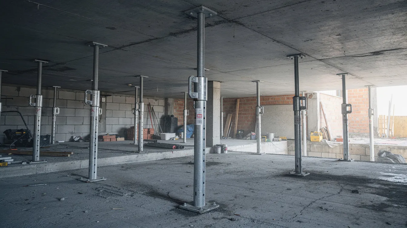
Adjustable steel Acrow props: Suitable for smaller spans and moderate loads. A Size 0 adjustable steel prop supports a safe load of 42 kN, with height adjustment achieved through the inner tube and outer tube, while larger configurations can support loads exceeding 1,000 kN per leg. Propping systems can support loads exceeding 1,000 kN per leg when heavy-duty towers or ganged arrangements are used.
-
Modular steel towers: For larger load transfer requirements and multi-floor back-propping scenarios where concentrated loads must be distributed through several storeys
-
Needle beam systems: Steel beams inserted horizontally through walls to transfer loads laterally when vertical access is restricted – particularly useful in existing buildings with limited headroom
Load transfer in propping must follow a continuous trajectory to the foundation. Every prop must sit on a base that can distribute its load without punching through the floor below, and every prop head must engage the slab above without creating stress concentrations, with the same principle applying where props support formwork carrying wet concrete during staged permanent works.
Pre-Installation Site Assessment
Before any propping is installed, a thorough assessment of the existing structure is essential, and environmental factors such as water ingress or site exposure can affect temporary support assumptions even for internal works. Propping is typically employed during alterations and remodeling of structures, but every building presents unique conditions:
-
Scan existing slabs using ground-penetrating radar or concrete scanners to locate reinforcement bars, post-tensioning tendons, and embedded services – avoiding cutting through critical reinforcement or, worse, prestressing cables
-
Assess supporting floor load capacity below the cutting level: the lower floors must be checked for bearing capacity, reinforcement adequacy, and column load limits, since back-propping imposes additional concentrated loads that may exceed original design assumptions
-
Review archival structural drawings to confirm slab thickness, reinforcement layout, beam positions, and column grid – noting that as-built conditions frequently deviate from original plans
-
Plan prop layout to avoid conflicts with existing MEP services, plumbing, HVAC ducts, and access requirements – coordinating with services drawings to ensure props can be positioned where the PE’s design requires them
This pre-installation assessment directly informs the PE’s design. Without accurate site data, even the most rigorous structural calculations may be based on incorrect assumptions.
Installation Sequence and Safety Protocols
The installation sequence for temporary propping follows a strict protocol designed to ensure that loads are never unsupported at any point during the operation. Propping provides vertical support during construction or repair, and the sequencing must reflect this:
-
Install props with 10–15% preload – tightening the adjustable mechanism so that the prop is already engaged and bearing load before any slab material is removed. This eliminates the dangerous gap between cutting and load transfer
-
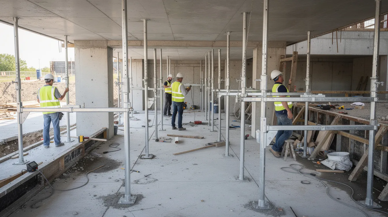
Verify prop installation through PE or site supervisor inspection: check alignment (no lean), head and base plate seating, lateral bracing connections, and that grillage plates or steel sheets are properly positioned to spread concentrated loads
-
Begin cutting operations only after written PE verification that the temporary support system is correctly installed and capable of carrying the anticipated loads
-
Monitor deflections during cutting using precision leveling instruments, dial gauges, or laser levels – the PE should specify acceptable deflection limits (typically L/360 under live load or as per code) and a schedule of readings
-
Install permanent reinforcement – edge beams, trimmer bars, or other strengthening measures – following the approved structural drawings
-
Remove props only after permanent modifications are complete, the concrete has achieved design strength, and the PE has confirmed that the permanent structure can safely carry all design loads independently
Temporary propping systems must be inspected at least every 7 days during the period they remain in place. Propping transfers weight directly down to a stable foundation during structural alterations, and any shift, settlement, or misalignment must be detected and corrected immediately.
Common Challenges and Engineering Solutions
Internal slab cutting in existing buildings rarely proceeds without complications. The challenges below represent the most frequent issues encountered on Singapore construction sites, along with their engineering solutions.
Inadequate Load Transfer to Lower Floors
When propping systems transfer vertical loads downward, the floor immediately below the cutting level may not have been designed to carry these additional concentrated loads. This is particularly problematic in older buildings where slab thickness may be marginal or reinforcement may have degraded.
Solution: Implement back-propping through multiple floors to distribute loads progressively to the foundation level. Use steel grillage plates or concrete pads at prop bases to spread concentrated loads over larger floor areas, reducing the risk of punching shear or local overstress. The PE must check each intermediate floor’s capacity as part of the overall propping design. Repair work may require hydraulic jacks and shoring towers to support damaged structures if existing floors show signs of distress.
Limited Access for Prop Installation
In occupied buildings, tight room layouts, low ceilings, and existing services can make it physically impossible to install standard vertical supports in the ideal positions. This is one of the most common mistakes contractors encounter – assuming props can go wherever the calculation shows they should.
Solution: Deploy needle beam systems to transfer loads horizontally through parallel walls or structural partitions when vertical access below is restricted. Use lightweight aluminium props in spaces with reduced headroom clearance, understanding that these typically have lower load ratings and may require closer spacing. In some cases, temporary rerouting of services may be necessary to clear prop positions – a coordination exercise that should occur during the pre-installation assessment phase, not during installation.
Vibration and Deflection During Cutting
Cutting concrete generates vibration, and vibration introduces dynamic loads that propping systems must resist without failure. Jackhammering is particularly problematic, producing impact forces that can cause lateral loads on props, contribute to fatigue in connections, and induce cracking in adjacent slab areas. Demolition stabilization uses vertical props to stabilize a building during dismantling, and similar principles apply during cutting operations.
Solution: Specify low-vibration cutting methods such as diamond wire sawing or diamond disc cutting instead of jackhammering. These methods produce cleaner cuts with minimal dynamic loading. Install additional lateral bracing and bracing members to prevent prop buckling under any residual dynamic loads. Monitor vibration levels using accelerometers if the PE determines that the existing structure is sensitive to dynamic effects.
Structural Uncertainty in Existing Buildings
Archival drawings may be incomplete, inaccurate, or unavailable. Hidden reinforcement layouts, undocumented modifications by previous owners, and concrete degradation from age or water ingress can all invalidate design assumptions. Where internal works interface with a masonry wall or similar load-bearing partition, the PE may need a different temporary support arrangement than for slab-only works.
Solution: Invest in thorough non-destructive evaluation before committing to a propping design. Concrete scanning reveals reinforcement positions and bar sizes. Core sampling confirms concrete strength. Visual inspection identifies cracking, spalling, or water damage. The PE should design with additional safety margins where uncertainty remains – can renovation works affect structural safety? is a question that must be answered with data, not assumptions.
Coordination with Building Services
Existing MEP installations – plumbing, electrical conduits, HVAC ducts, fire protection systems – frequently occupy the space where props need to stand or where needle beams need to pass. Services may also run through or be embedded in the slab section being cut.
Solution: Obtain and overlay services drawings with the structural propping layout before installation. Where conflicts exist, coordinate temporary service diversions with the relevant trades. The PE and MEP engineer should review the propping plan jointly to identify and resolve conflicts before mobilisation. Propping is essential during the installation of masonry reinforcement and other permanent works, and services coordination ensures that this essential support can be positioned correctly.
Conclusion and Next Steps
Temporary propping for internal slab cutting is not optional engineering – it is a legal requirement and a technical necessity in Singapore. PE structural calculations ensure that load paths remain continuous, that safety factors meet or exceed those of permanent works, and that every stage of the cutting and reinforcement sequence is designed to maintain safety. Shoring systems are critical during excavation to prevent collapse, and the same principle applies with equal force to internal structural modifications. There are 12 types of shoring methods in construction, and selecting the right approach for internal slab cutting requires engineering judgment grounded in site-specific analysis.
Immediate action items for your next project:
-
Engage a qualified PE at the earliest planning stage – before finalising opening locations or construction timelines. Early PE involvement allows temporary works design to proceed in parallel with permanent design, avoiding costly delays
-
Obtain BCA approvals with complete submission packages including structural drawings, calculation books, method statements, and temporary works details
-
Implement comprehensive monitoring protocols – deflection measurements, prop inspection at minimum 7-day intervals, and PE sign-off before cutting commences and before props are removed
-
Document everything – daily monitoring logs, photographs of prop installation, PE verification records. These protect all parties and satisfy regulatory requirements
For related considerations, explore permanent structural strengthening options for post-cutting reinforcement design, A&A works scope classification to determine your project’s regulatory category, and construction method statement requirements for preparing compliant documentation.
Frequently Asked Questions
When is PE endorsement required for internal slab cutting in Singapore?
PE endorsement is required whenever works materially affect structural elements. Internal slab cutting is a structural alteration by definition – it severs reinforcement and changes load paths. The PE must endorse drawings and calculations for both the temporary propping arrangement and the permanent structural modifications. Where risk is high or the project involves critical structural elements, an Accredited Checker must independently verify the PE’s design. Facade retention is critical during interior demolition to preserve structural front facades, and similar PE oversight applies to any work that compromises structural integrity.
What are the typical costs for temporary propping design and installation?
PE calculation and design fees typically run several thousand Singapore dollars depending on project size and complexity. Prop rental costs vary – adjustable steel props may cost hundreds of SGD per prop per day, with modular steel towers commanding higher rates. Installation labour, grillage plates, lateral bracing, and monitoring equipment add to the total. For a detailed breakdown of PE endorsement costs, the range depends heavily on the number of openings, the number of floors affected, and whether AC involvement is required.
How long does BCA approval take for structural modification projects?
For Structural Plan applications without Accredited Checker certification, BCA processes complete submissions within 7 working days. With AC involvement, first submissions may take 10 working days, with subsequent submissions taking up to 14 working days. Temporary works submissions (PTU) may be bundled with the ST plan or submitted separately, potentially adding time depending on complexity. Contractors should begin the submission process well before planned commencement to avoid site idle time.
What happens if temporary props fail during cutting operations?
Prop failure during slab cutting can cause localised collapse or dramatic deflection of the slab section being supported. Academic studies examining sudden failure of shoring elements under successive slabs have documented how loss of a single prop can trigger cascading overload of adjacent props and catastrophic failure. Consequences include physical injury, damage to finishes and services on lower floors, and legal liability under the Building Control Act – including potential loss of permits and insurance coverage. This is why redundancy, staged removal, deflection monitoring, and adherence to PE-specified tolerances are non-negotiable. Timber shoring is one of the oldest methods used in construction, but modern construction demands engineered steel systems with verified load ratings for structural applications.
Can existing building services interfere with prop installation?
Yes. Existing MEP, plumbing, HVAC ducts, and electrical conduits frequently occupy positions where props need to be placed or where needle beams need to pass. Services may also be embedded within or attached to the underside of the slab being cut. The solution is to obtain services drawings, overlay them with the propping layout during design, and coordinate temporary diversions with the relevant trades before mobilisation. Hydraulic shoring uses pistons to prevent trench wall collapse in excavation contexts, and similar space-coordination principles apply in building interiors. H and I-beam shoring supports deep excavations in urban areas, but for internal works, the focus shifts to managing conflicts with building services rather than soil conditions.
What monitoring is required during slab cutting operations?
The PE should specify a monitoring regime that includes regular deflection measurements using precision leveling instruments or dial gauges, visual inspection of props for alignment, bearing, and lateral bracing integrity, and vibration monitoring where dynamic cutting methods are used. The PE may also specify checks for any support members set in a raking position if the temporary arrangement cannot rely on purely vertical props. Acceptable limits for deflection and vibration should be defined before works commence, with clear remedial actions specified if thresholds are exceeded. Secant pile shoring prevents groundwater ingress in excavations, and while the context differs, the principle of continuous monitoring during critical operations is universal. Shoring is used to manage lateral pressures in excavations, and the same discipline of measurement-based safety applies to internal propping operations.
How do you determine if lower floors can support back-propping loads?
The PE must check the slab thickness, reinforcement layout, concrete strength, column grid spacing, and bearing capacity of each floor that will receive back-propping loads. This requires reviewing original structural drawings, potentially scanning reinforcement in lower floors, and calculating whether the additional concentrated loads from props – combined with the floor’s existing dead and live loads – remain within the structural capacity of each element. Ground conditions and foundation adequacy must also be confirmed where props transmit loads to the lowest level. Ensuring stability through the entire load path – from the cut slab down through every intermediate floor to the foundation – is the PE’s core responsibility in back-propping design.