
Introduction
Shop drawing production for steel connections clash detection and coordination best practice is, at its core, a model-driven discipline: steel connection geometry is developed to at least LOD 300–350 in BIM, structured clash detection cycles are run against all interfacing trades, and a Qualified Person or Professional Engineer endorses critical connections before fabrication begins. On industrial steel projects-process plants, warehouses, pipe rack structures, and heavy logistics facilities-this workflow is the single most effective defence against costly rework, site delays, and authority rejections.
This article focuses specifically on structural steel connections and their coordination with major trades (process steel, heavy MEP, pipe racks, platforms) through building information modeling. It is not a steel design textbook. The scope is the production, coordination, and clash-proofing of connection shop drawings on industrial projects in Singapore and the wider region, where BCA structural plan submissions, SCDF fire safety clearances, and specialist builder licensing impose strict requirements on what fabrication drawings must contain.
The intended audience is contractors, steel fabricators, construction professionals, and industrial facility owners who need constructible, authority-compliant coordination on current or upcoming projects. By the end of this guide, you will gain:
-
A clear understanding of what steel connection shop drawings must include for industrial buildings
-
A repeatable, step-by-step clash detection and coordination workflow you can deploy immediately
-
Minimum modelling standards and checklists for BIM-based connection detailing
-
Awareness of common pitfalls that derail project execution-and proven solutions
-
Clarity on Singapore authority requirements and how PE endorsement fits into the process
Understanding Steel Connection Shop Drawings
Steel connection shop drawings translate a structural engineer’s design intent into the precise fabrication and erection information that a workshop floor needs. They define every plate, bolt, weld, and stiffener at a level of detail that design drawings intentionally omit-and on industrial projects, where multiple trades compete for the same physical space, their accuracy directly determines whether steel arrives at site clash free or requires expensive field modifications.
What Steel Connection Shop Drawings Actually Show
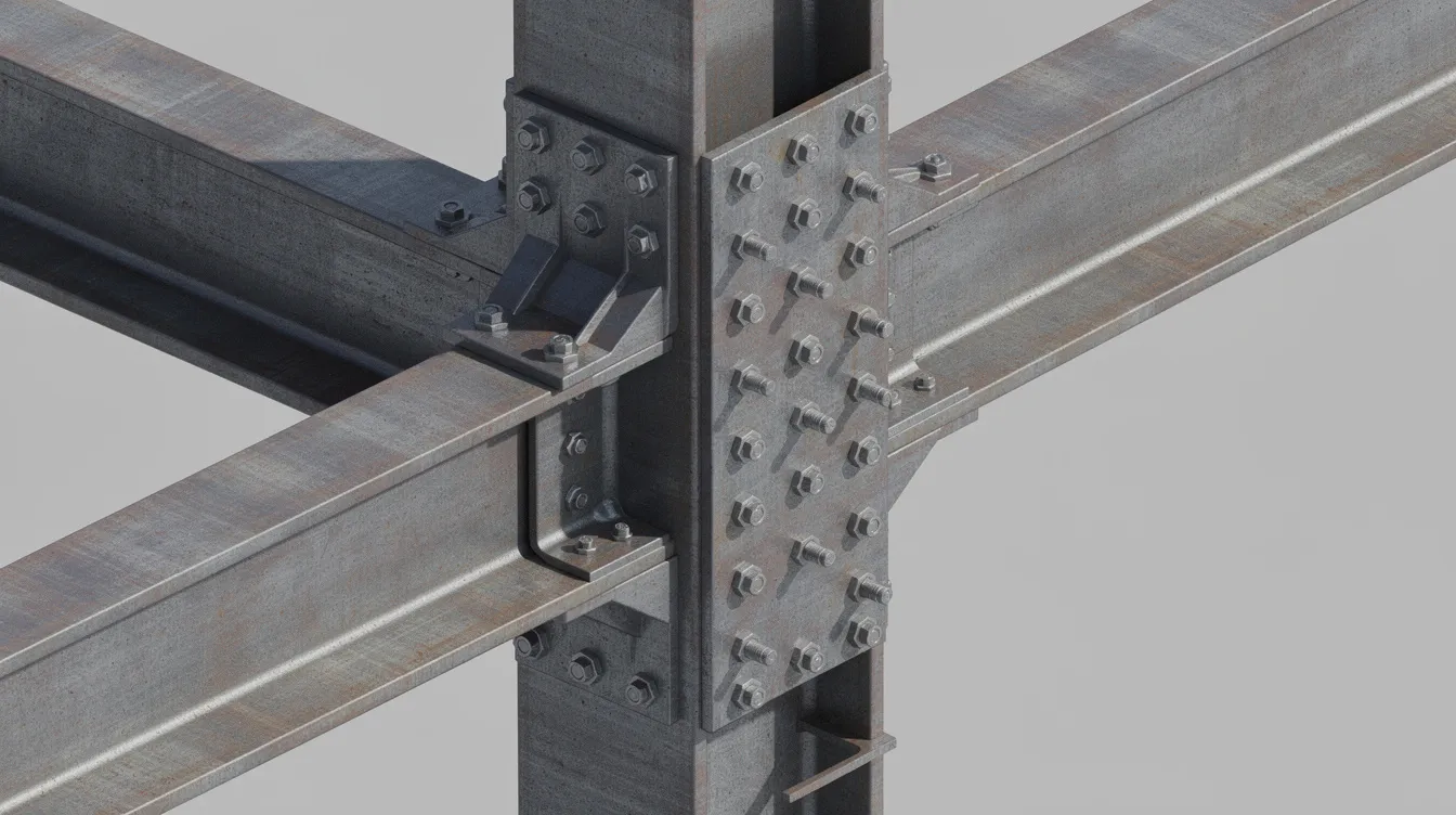
Design drawings specify member sizes, spans, and global framing. Shop drawings go several layers deeper: exact plate sizes and thicknesses, bolt grades and types (e.g. ASTM A325 or equivalent metric fasteners per ISO 4014), hole patterns with edge distances, welding methods (bevel types, weld sizes, symbols), stiffener locations, base plate dimensions, and anchor bolt layouts. Structural steel shop drawings must model exact hardware geometry-every gusset, every end plate, every lifting lug.
The distinction between a General Arrangement (GA) drawing and a single-part or assembly drawing is fundamental. The GA shows overall framing, grid systems, and member locations across the building. Assembly drawings show a fabricated unit-say, a beam-to-column assembly complete with stiffeners and connection plates-including weight, centre of gravity, and shop welds. Single-part drawings isolate each loose plate, angle, or bracket with its precise hole drilling pattern and finish.
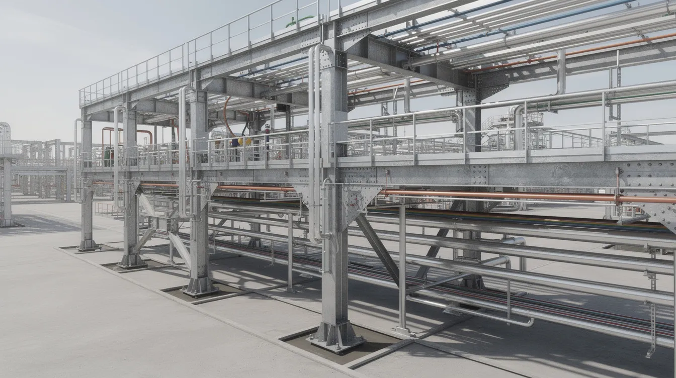
For industrial steel specifically, drawings must show interfaces with equipment supports (vessels, tanks, pumps), pipe shoes, platforms, walkways, catwalks, and ladders. These interface details are where most coordination failures occur. Typical content on a connection shop drawing includes:
-
Member designations and assembly/part marks
-
Plate, angle, stiffener, and bracing component dimensions and profiles
-
Bolt types, grades, hole sizes, spacing, and pattern layouts
-
Welding types, sizes, processes, and weld symbols
-
Anchor bolts, base plates, levelling, and grouting requirements
-
Surface treatment specifications (galvanising, paint systems)
-
Fabrication tolerances, erection marks, and crane lifting points
-
Material schedules: steel grades, plate thicknesses, weights
-
NC/CNC files or DSTV export data for fabrication machines
Shop drawings provide detailed information for manufacturing and assembly-and when they are incomplete or inaccurate, fabrication inconsistencies ripple through the entire construction project.
Roles and Responsibilities in Connection Detailing
On Singapore and regional industrial projects, connection detailing involves a clear split of responsibilities that project teams must understand from day one.
The Structural Engineer of Record (SEOR) / Professional Engineer (PE) is responsible for structural design, global member sizing, load paths, and code compliance. For critical connections-crane runway beams, plate girder splices, pipe-rack portal frames-the SEOR typically designs or closely reviews the connection and must certify the design calculations for authority submission.
The steel detailer and fabricator creates the fabrication model, produces shop drawings, selects connection types within the design requirements, and handles constructability decisions: ease of access for bolting or welding, standard plate thicknesses, welding procedures, and fabrication tolerances. They generate NC data for workshop machines. Modern shop drawing workflows support fabrication-ready project delivery when the detailer is given clear design parameters.
The main contractor / BIM coordinator ensures multidisciplinary BIM coordination across steel, MEP, process, and architectural elements. They trigger clash detection cycles, enforce naming conventions and modelling standards, and interface with procurement and erection sequencing. Coordination meetings facilitate communication between project stakeholders and keep the workflow moving.
An independent A&E/PE consultant-such as AEC Technical Advisory-can review connection details and shop drawing sets for compliance with BCA, SCDF, and other regulatory requirements, endorse drawings where required, and audit consistency between the coordinated model, design calculations, and authority-approved structural plans.
Key accountability split:
-
SEOR/PE: global loads, connection design for critical or non-standard joints, endorsement for authority submission, material and design specifications
-
Fabricator/Detailer: connection modelling, shop drawing generation, NC files, manufacturing readiness
-
BIM Coordinator: federated models, clash detection, discipline alignment, schedule, conflict resolution
-
Independent Reviewer: certifying that connection details comply with codes; ensuring shop drawings reflect approved structural plans
From Design Model to Fabrication Model
The engineer’s analysis or design model-typically built in tools like SAP2000, ETABS, or STAAD-focuses on members, loads, and global stability. Connections may be analysed for forces but are rarely modelled with full geometric detail. The fabrication model, built in detailing software such as Tekla Structures or Advance Steel, adds every connection plate, stiffener, bolt, and weld as 3D solids. This is the model from which shop drawings, 3D models, and fabrication data are extracted.
The critical concept here is Level of Development (LOD). At LOD 300, the structural member has specific geometry and orientation, but connections are often represented symbolically. At LOD 350, connection elements-base plates, gussets, anchors, stiffeners-are modelled with enough geometric accuracy for coordination with other trades. At LOD 400, full fabrication information is present: every loose part, weld detail, hole location, and NC-ready data. Steel connection shop drawings require high-fidelity 3D modeling for clash detection, and only once the model reaches LOD 350 does meaningful bim clash detection become possible.
From Concept to Coordination: Applying BIM to Steel Connection Shop Drawings
With the fabrication model built to the right level of development, the focus shifts to coordination-aligning the steel connection geometry against every other discipline model that occupies the same zone. This is where BIM coordination prevents conflicts between structural steel and MEP services before a single piece of steel reaches site.
Model Requirements for Reliable Clash Detection
Accurate 3D models help visualize the geometric relationship of connections, but only if the geometry is actually present. For reliable clash analysis, all connection plates, stiffeners, base plates, anchor bolts, and gussets must be modelled as 3D solids. Any connection component above a threshold size-typically plates thicker than 8 mm, all stiffeners, and all base plate assemblies-must appear in the bim model. Weld geometry should be included where it affects clearance with adjacent elements.
Minimum modelling standards for industrial steel coordination:
-
Primary steel connections (beam-to-column, column base, bracing nodes): modelled to LOD 350, including gussets, anchor bolts, base plates, and stiffener plates
-
Secondary steel (platforms, handrails, ladders): modelled with correct profiles; LOD may be lower if the area is not congested, but must be sufficient to detect spatial conflicts
-
All penetrations, embed plates, pipe shoes, and equipment support interfaces that interact with steel: represented with correct geometry and position
BIM software can identify hard and soft clashes through geometric analysis, but only against geometry that exists in the model. Omitting a 25 mm stiffener plate from a beam-to-column node means the clash detection software will report the zone as clash free-and the clash will appear on site instead. Manufacturers should conduct clash detection to avoid costly field modifications, and the quality of that detection depends entirely on model completeness.
The Singapore BIM Guide Version 2 emphasises establishing a clash detection matrix and multi-disciplinary coordination protocols to reduce false positives and ensure meaningful results.
Coordinating Steel Connections with Other Disciplines
Steel connection geometry commonly clashes with large-diameter process pipes, cable tray runs, heavy ducting, tray supports, and mechanical equipment foundations. On industrial projects, the congestion is concentrated at specific nodes-pipe rack portal frames, mezzanine support points, equipment module interfaces-where multiple trades converge in the same space.
Typical coordination pairings include:
-
Steel vs major equipment: vessel support brackets, tank saddle connections, and pump bases often require stiffeners or gussets that project into areas claimed by process piping or electrical conduit
-
Steel vs MEP services: a structural beam with a bolted end-plate connection may clash with a cable tray routed beneath it, or a stiffener may block a pipe support shoe
-
Steel vs fire-rated enclosures: in hazardous-area industrial buildings, fire-rated walls and barriers must interface cleanly with steel framing; connection plates cannot bridge fire compartment boundaries unprotected
Singapore authority considerations add further constraints. SCDF fire safety requirements mandate minimum headroom over escape routes-steel connection eccentricities or lifting lugs cannot encroach on these clearances. Connection plates and stiffeners must not obstruct sprinkler deflector clearance or spray patterns. Maintenance access around AHUs, pumps, and filter assemblies is routinely enforced; platform support connections must be positioned to allow equipment servicing. These are not optional refinements-they are authority approval requirements that can halt a project if missed.
M&E coordination must be integrated into the steel coordination workflow from the start, not bolted on after steel detailing is complete.
Deliverables: What a Coordinated Shop Drawing Set Includes
A well-coordinated shop drawing set for industrial steel connections includes the following key outputs:
-
GA framing plans and elevations with assembly and part marks, grid and level designations
-
Connection detail sheets: one sheet per unique connection type, cross-referenced to structural member sizes and design notes
-
Assembly drawings: for fabrication and shop fit-ups, showing weight, centre of gravity, shop welds
-
Single-part drawings: for each loose plate, bracket, and fitting, with hole drilling patterns
-
Bolt and plate material schedules: bill of materials listing plate types, grades, lengths, and bolt quantities
-
NC/DSTV/control files: machine-readable data for CNC cutting, punching, and drilling
-
3D coordination views and isometrics: particularly for congested zones such as pipe rack joints and equipment modules
Coordinated shop drawings improve communication among project stakeholders by making complex spatial relationships visible. Integrated shop drawing systems reduce fabrication inconsistencies by ensuring every drawing and NC file traces back to the same coordinated model.
Before approving a “final” shop drawing issue for construction, project managers should verify:
-
All discipline models have been federated and clash detection passed with critical clashes resolved
-
All connection details have been PE-reviewed and endorsed where required
-
Shop drawings match the approved structural plan submissions and design calculations
-
Fabrication deliverables (NC files, schedules) are consistent and include tolerance and material finish notes
-
Shop drawings use a unified coordinate system to ensure accuracy across disciplines
-
3D views of congested zones are included for site reference
With deliverables defined, the next step is establishing the process that produces them reliably and repeatably.
Best‑Practice Workflow for Shop Drawing Production and Clash Detection
This section provides the practical, step-by-step coordination workflow used on BIM-enabled industrial steel projects. Implementing a structured workflow is crucial before detailing begins-without it, even the best software and the most skilled teams produce fragmented results.
Step‑by‑Step Coordination and Production Process
-
Establish the BIM Execution Plan (BEP): Define responsibilities, model deliverables, LOD targets per stage (members first, connections second), model exchange intervals, naming conventions, clash rules, and allowable tolerances. The bim execution plan is the contract among project teams for how coordination will work.
-
Develop the analytical and design model: Freeze grid lines, primary structural member sizes, and global framing. The structural engineer provides preliminary connection design for critical connections (e.g. portal frames, crane beams), even if connection solids are still symbolic at this stage.
-
Build the fabrication model with detailed connections: Produce the member and connection model in Tekla Structures, Advance Steel, or similar software. Connections are detailed to LOD 300–350, including base plates, gussets, stiffeners, and anchor bolts. Establishing clear tolerances improves connection installation accuracy from this point forward.
-
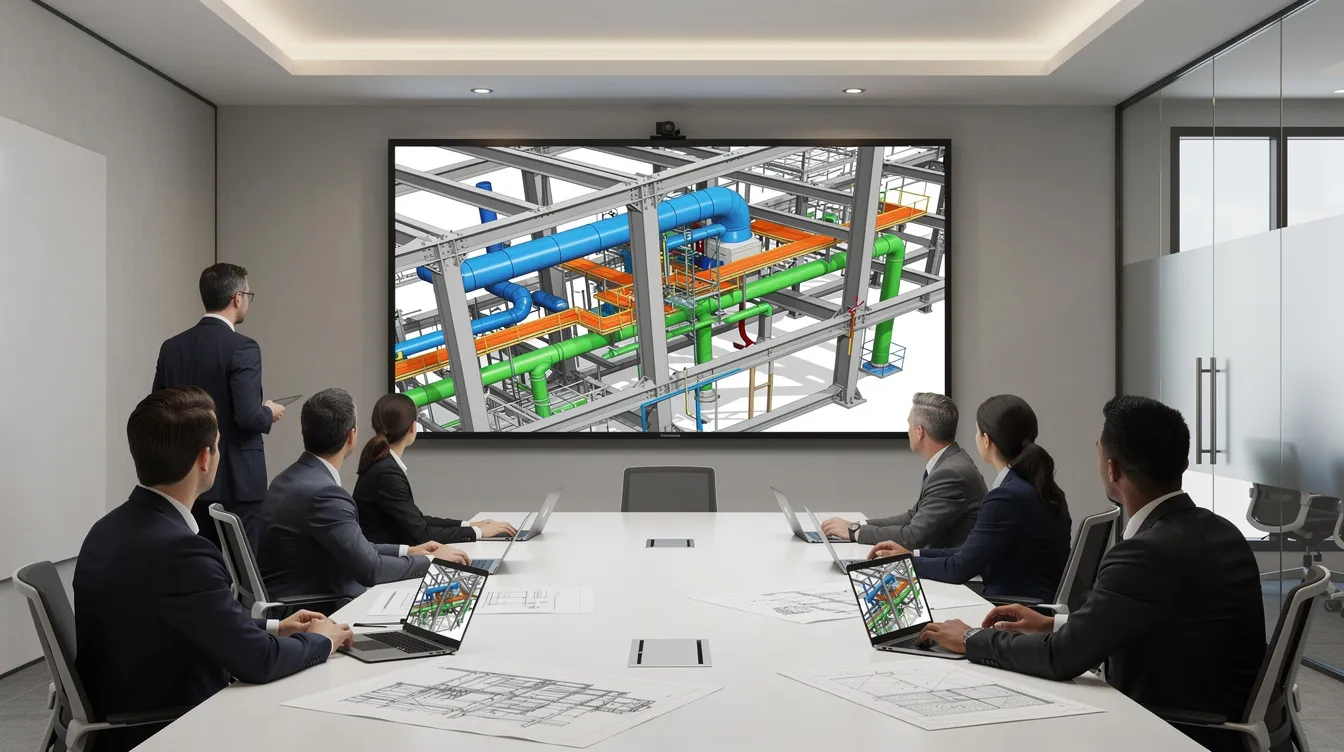
Federate models from all disciplines: Combine structural, MEP, process, architectural, and equipment models. Align coordinate origins and coordinate systems. Use federation tools such as Navisworks Manage or BIMcollab Zoom to create the federated models that form the basis for spatial coordination.
-
Run structured clash tests: Focus on steel connections vs MEP services, steel vs mechanical equipment and process piping, steel vs access routes and fire-safety zones. Hard clashes occur when components occupy the same physical space. Soft clashes arise from insufficient spatial tolerances between components-for example, a gusset plate that leaves little room for a wrench to reach an adjacent bolt. Workflow clashes involve scheduling conflicts during construction timelines, such as steel erection sequencing vs MEP rough-in. Automated clash detection should occur during the detailing phase to catch issues before fabrication.
-
Review, classify, and assign clashes in coordination meetings: Weekly during peak detailing. Classify by severity and relevance (true clash vs false positive). A clash detection matrix can assign ownership to resolve conflicts-each clash goes to a discipline owner with a resolution deadline. Grouping similar clashes by part or assembly reduces overhead. Issue tracking ensures nothing falls through the cracks.
-
Implement approved changes: Update the steel model and connection details accordingly. Ensure changes are documented, version-controlled, and communicated. Formal approval processes validate design changes affecting connections.
-
Generate shop drawings, CNC/NC data, and material lists: Extract all fabrication deliverables from the updated, coordinated model. Shop drawings help organize structural assemblies before production. Regular peer audits can ensure quality in shop drawings at this stage.
-
Obtain PE/Qualified Person review and endorsement: Required for critical steel connections, authority submissions to BCA and SCDF, and compliance with the COP-SG submission requirements. Steel connections must comply with structural engineer’s design requirements and code provisions.
-
Lock for fabrication and issue controlled revisions: During construction, changes proceed only through formal change management. BIM coordination reduces unnecessary changes during construction and protects the integrity of what has been coordinated.
Comparing Coordination Approaches for Industrial Steel Projects
Different coordination setups suit different industrial project types and budgets. The choice depends on project scale, risk profile, and the team’s in-house BIM capability.
|
Criterion |
2D‑Led with Limited 3D |
Full 3D Federated BIM with Model‑Derived Shop Drawings |
|---|---|---|
|
Typical use case |
Small warehouses, simple industrial buildings with minimal MEP/process congestion |
Large process plants, pipe racks, heavily serviced industrial factories |
|
Upfront effort |
Low; mostly 2D connection notation, minimal solid modelling |
High; detailed modelling from early design development, intensive coordination |
|
Clash detection reliability |
Poor; many potential conflicts missed until site, leading to costly rework |
High; most geometric intersections resolved pre-fabrication |
|
Impact on fabrication/erection |
Higher rework, ad-hoc fixes, delays, elevated rework costs |
Smoother erection, fewer site conflicts, better construction efficiency |
|
Suitability for prefabricated modules |
Low; insufficient data for off-site fabrication coordination |
High; model-derived data supports modular construction and prefabrication |
Projects with high risk-tight headroom, complex MEP and process steel interactions, heavy authority involvement, or fast-track commissioning schedules-should invest in full 3D federated BIM. Simpler industrial projects may adopt a hybrid approach, but congested zones (equipment modules, pipe rack portals, mezzanine platforms) should always receive full modelling regardless of overall project complexity. BIM can reduce rework costs by up to 40%, and on large industrial projects that translates directly into schedule and budget protection. Early clash detection can save tens of thousands of pounds-or far more on major industrial facilities. Detecting clashes virtually can save £800,000 on rework, as documented on infrastructure-scale projects.
Whichever approach is chosen, the coordination workflows must account for authority and client requirements from the outset.
Integrating Authority and Client Requirements Early
For Singapore industrial projects, authority constraints from BCA, SCDF, LTA (for access), and PUB (for drainage interfaces) must be built into the bim model before finalising connection details-not patched in afterward. Clash detection should be integrated into the detailing process early, and that includes regulatory clearances.
Concrete examples of authority-driven coordination:
-
Clearance to fire sprinklers below roof steel: Truss connection brackets and gusset plates cannot interfere with sprinkler deflector clearance or spray patterns. A stiffener plate projecting 50 mm below the bottom flange of a roof beam may violate SCDF’s minimum clearance requirement-and this is exactly the type of conflict that bim clash detection catches when the sprinkler model is federated with the steel model.
-
Headroom over escape routes: SCDF and BCA mandate minimum heights over escape corridors. Connection eccentricities, lifting lugs, or base plate extensions projecting into corridors must be identified and resolved during coordination, not discovered during the authority inspection.
-
Maintenance access: Platform support connections and steel stair connections must allow access to AHU filters, pump servicing areas, and plant rooms. Authorities increasingly require that maintenance access paths be demonstrated in the model before approval.
BIM coordination helps identify conflicts before construction begins-including conflicts with regulatory requirements that are just as disruptive as physical clashes. AEC Technical Advisory has direct experience incorporating authority feedback into coordination models and producing PE-endorsed structural designs and shop drawings that satisfy BCA and SCDF requirements on industrial projects.

Common Coordination and Shop Drawing Pitfalls – and How to Avoid Them
Even with capable bim software and experienced engineers, recurring problems derail coordination and clash detection on industrial steel projects. Effective BIM coordination reduces costly rework and improves efficiency-but only when these pitfalls are addressed head-on.
Problem 1: Incomplete or Over‑Simplified Connection Modelling
Issue: Connections are modelled symbolically or omitted entirely, producing a coordinated model that appears clash free but generates interference the moment steel arrives on site. A missing 20 mm stiffener plate, an unmodelled anchor bolt group, or an absent gusset allows clash detection software to report zero conflicts-while the site team faces two objects trying to occupy the same physical space.
Solution: Mandate a minimum modelling standard: all connection plates and stiffeners above 8 mm, all base plates, all anchor bolts and embed plates must be modelled as 3D solids. Include random spot-checks by the PE or BIM coordinator before each clash detection cycle. Identifying clashes early reduces construction costs and project delays-but only if the geometry is actually in the model. Clash detection helps identify spatial conflicts before fabrication, provided the model is complete.
Problem 2: Late Involvement of Fabricator and Detailer
Issue: When the fabricator is brought in only after the design is frozen, design decisions-connection types, bolt sizes, welding processes, non-standard plate thicknesses-may be impractical for the workshop or site. Late adjustments cause rework on both the model and the shop drawings, and procurement of long-lead items is delayed.
Solution: Involve the fabricator and detailer during design development so their practical preferences (standard plate thicknesses, bolt types available in the region, preferred welding procedures) inform the connection model from the outset. On fast-track industrial projects with tight commissioning dates, early detailer involvement can compress the critical path by weeks. Effective coordination minimizes requests for information during construction and avoids the back-and-forth that consumes schedule.
Problem 3: Poor Change and Revision Control
Issue: Untracked design changes-altered equipment loads, new openings, revised MEP routing-create mismatches between the PE-endorsed drawings and what is actually fabricated. Different disciplines work from different model versions. The site builds from outdated shop drawings. Data clashes occur due to inconsistencies in cost estimations or specifications between disconnected documents.
Solution: Implement strict revision protocols: unique drawing revision numbers, change logs, and timestamps within the BIM environment. Designate a single “source of truth” model that all fabrication deliverables are extracted from. Sharing a common data environment enhances collaboration among teams and eliminates the version-control chaos that plagues projects with fragmented file management. AEC Technical Advisory can act as an independent reviewer to audit consistency between models, shop drawings, and authority-approved plans.
Problem 4: Ignoring Construction and Erection Sequencing
Issue: Connections that work perfectly in a static 3D model may be impossible to erect or bolt in the sequence available on a congested industrial site. A bolted splice may require wrench access that disappears once adjacent steel is in place. A welded connection may need overhead access that a platform above blocks. Reducing errors in geometry means nothing if the erection crew cannot physically install the connection.
Solution: Incorporate 4D thinking into coordination reviews. Simulate erection sequencing; ensure connections are oriented for bolting and welding accessibility; verify crane reach and pick-point clearances; model temporary bracing requirements. BIM for temporary works can be integrated into the coordination process to ensure that what is coordinated in the model can actually be built in the field. Early clash detection can protect project schedules significantly by catching not just geometric intersections but also constructability conflicts.
Conclusion and Practical Next Steps
Robust, BIM-driven shop drawing production for steel connections-paired with structured coordination and clash detection-is the most cost-effective risk control available on industrial projects. It shifts conflict resolution from the site (where changes cost ten times more) to the model (where they cost a fraction). Effective BIM coordination improves project delivery timelines, reduces site rework, and produces shop drawings that fabricators can trust and authorities can approve. BIM clash detection reduces rework costs by up to 40%, and on complex industrial steel projects, those savings compound across every connection node, every pipe rack bay, and every equipment support.
To apply these practices on your current or next construction project, take these steps immediately:
-
Define connection modelling standards for your project: specify LOD targets, minimum plate/bolt modelling thresholds, and QA spot-check frequency
-
Set up a clash detection matrix that pairs steel connections against MEP, process, equipment, access routes, and fire safety elements-and assign ownership for each clash category
-
Schedule regular coordination meetings during peak detailing (weekly at minimum) with representation from structural, MEP, process, and the fabricator
-
Appoint a single model owner responsible for version control and the “source of truth” coordinated model
-
Engage your PE reviewer early for critical connections so that endorsement and authority submission run parallel to detailing, not after it
-
Integrate authority requirements (BCA, SCDF, maintenance access) into the BIM model before the first clash detection cycle, not as a late-stage patch
Related topics worth exploring include temporary works design for steel erection, FEM analysis for complex steel connections, and integration of façade and roof systems with industrial steel frames.
AEC Technical Advisory delivers PE-endorsed structural design, BIM coordination, and shop drawing reviews for industrial facilities in Singapore and the region. Contact us with your current project details to review your existing steel connection shop drawing and coordination approach.
Additional Resources and Coordination Checklists
This section offers concise tools rather than theory-resources your project teams can apply directly.
Steel Connection Coordination Checklist (for Industrial Projects)
Model Completeness Checks:
-
All primary structural members modelled with correct profiles, orientations, and positions
-
All connection plates, stiffeners, gussets, and base plates above 8 mm modelled as 3D solids
-
All anchor bolts, grout pockets, and embed plates modelled
-
Equipment support interfaces, pipe shoes, and platform connections represented
-
Weld geometry modelled where it affects clearance with adjacent systems
Clash Test Scope:
-
Steel connections vs MEP services (piping, cable tray, ducting, electrical conduit)
-
Steel connections vs mechanical equipment and process piping
-
Steel connections vs access routes, escape corridors, and maintenance zones
-
Steel connections vs fire strategy elements (sprinklers, smoke vents, fire-rated enclosures)
-
Soft clashes checked for bolt access, wrench clearance, and welding reach
-
BIM clash detection improves efficiency by identifying conflicts early; clash detection can minimize delays in construction schedules when the test scope is comprehensive
Shop Drawing QA Checks:
-
Dimensions verified against design model and PE-endorsed calculations
-
Welding details complete (weld type, size, process, symbols)
-
Bolt schedules accurate (grade, type, quantity, hole size)
-
References to design notes and PE endorsement included on each sheet
-
Drawing revisions tracked with unique numbers, change logs, and timestamps
-
NC/DSTV files verified against assembly drawings
-
BIM models help visualize complex spatial relationships clearly-include 3D views for congested zones
Site Feedback Loop:
-
Process for erection teams to report fit-up issues back to the BIM coordinator
-
Mechanism to update standards and modelling protocols based on recurring site issues
-
As-built model updated to reflect field conditions for handover and future A&A works
How AEC Technical Advisory Supports Industrial Steel Projects
AEC Technical Advisory provides integrated engineering services for industrial steel projects, combining structural design capability with BIM coordination expertise. Our team produces fabrication-grade structural models and connection details that feed directly into coordinated shop drawing sets-ensuring that what is designed, what is modelled, and what is built are one and the same.
For clash detection and multidisciplinary bim coordination, we federate steel models with process, MEP, and architectural disciplines to identify and resolve design conflicts before they reach site. Our coordination workflows are structured around the bim process standards required by Singapore authorities, including COP-SG modelling requirements and the BCA Design Guide for Buildable Steel Connections.
We handle authority submissions and PE endorsements for BCA structural plan approval, SCDF fire safety compliance, and related regulatory pathways-directly linked to coordinated shop drawings and the underlying BIM model. For existing plants undergoing additions and alterations, we provide on-site inspections, structural assessments, and as-built model updates.
If your industrial project needs steel connection coordination that is constructible, authority-compliant, and fabrication-ready, contact AEC Technical Advisory to review your current approach and identify where improvements will deliver the greatest impact.