
Introduction
Professional Engineers in Singapore can evaluate existing I-beams and concrete soffits for under-hung light hoist installations under 1-tonne capacity through dynamic load calculations, often without triggering full Additions & Alterations (A&A) building plan submissions. This pathway saves 6 to 12 weeks of approval time and reduces consultant fees compared to a full BCA structural plan submission.
This article covers the PE dynamic load analysis process for overhead monorail light hoists mounted to existing factory structures. It is written for facility managers, engineering teams, and operations planners in Singapore’s light industrial sector who need to add material handling capacity to existing workstations. The scope includes load calculation methods under SS 497:2011, structural evaluation of steel beams and reinforced concrete soffits, anchor selection, and the regulatory framework governing minor works versus full A&A submissions. Heavy overhead crane installations, new structural steelwork design, and bridge or gantry cranes requiring independent support structures fall outside this scope.
After reading this article, you will understand:
-
How PEs calculate dynamic load amplification factors for monorail hoist systems operating at different speeds
-
What structural checks are required for existing I-beam and concrete soffit supports
-
When hoist installations qualify as minor works versus when they require full BCA plan submissions
-
How to select and verify anchors for dynamic loading conditions in older factory buildings
-
Cost and timeline differences between PE endorsement and full A&A approval pathways
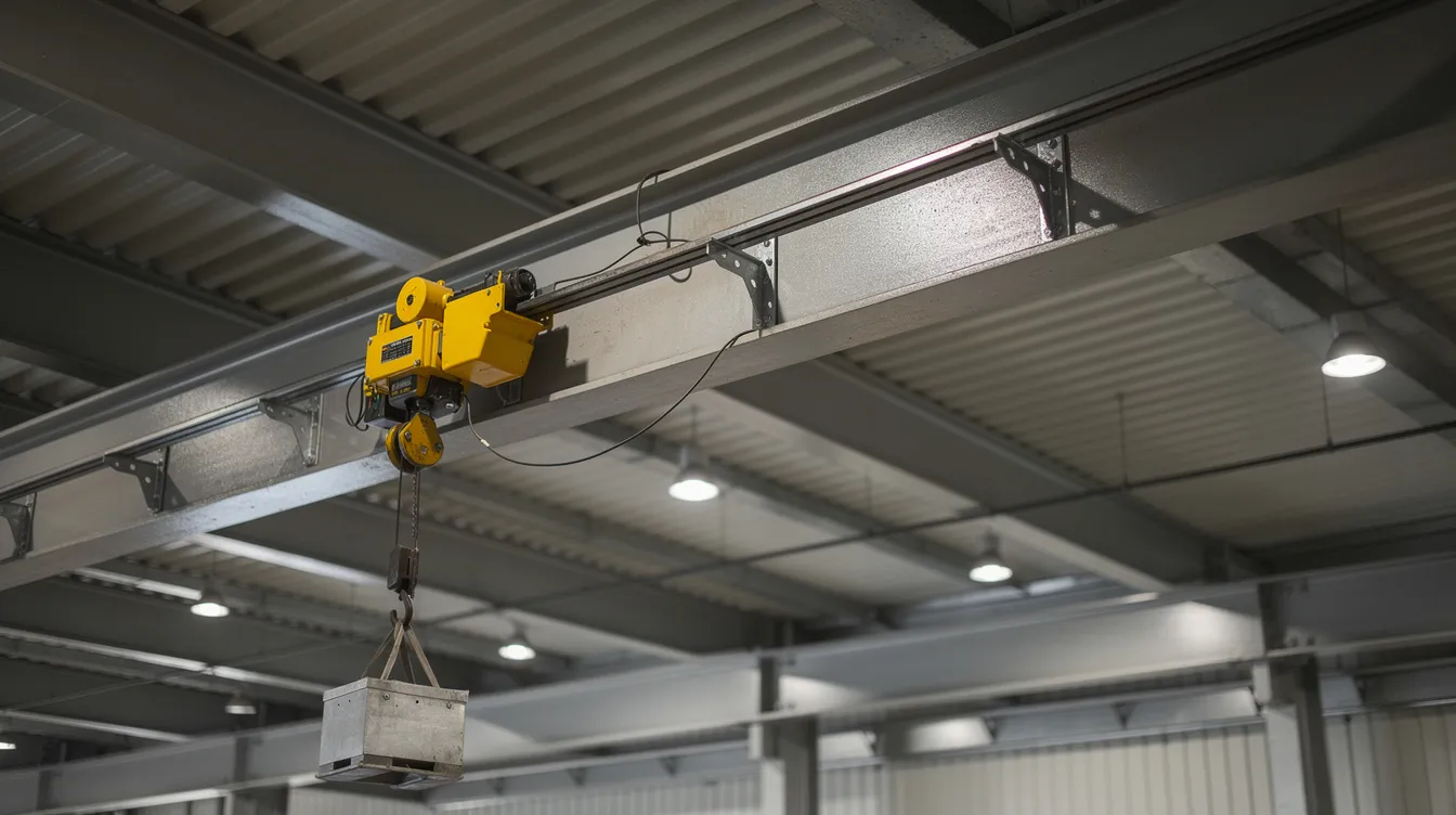
Understanding Dynamic Load Analysis for Light Hoists and Monorail Crane System
A monorail crane hoist suspended from an existing beam does not simply apply its rated payload as a static force; its core function is to carry loads along a fixed path, and every time the electric hoist accelerates upward, decelerates, or the load swings during trolley travel, the beam experiences forces that exceed the static weight. Quantifying these additional forces is what dynamic load analysis does, and it determines whether an existing structural member can carry a hoist without reinforcement.
Under Singapore’s Building Control Act, any work that materially affects key structural elements requires assessment by a Professional Engineer. For factory workstations adding monorail cranes as a material handling alternative where bridge or gantry equipment is impractical, PE evaluation is mandatory whenever the hoist load (including dynamic amplification) changes the loading condition of beams, columns, or foundations.
Static vs Dynamic Load Components
Static loads comprise the dead weight of the hoist equipment itself (motor, wire rope drum, housing, trolley, monorail beam attachments) plus the maximum lifted payload. For a 1,000 kg rated electric monorail hoist, the equipment typically weighs 150 to 250 kg, bringing the total static load to roughly 1,150 to 1,250 kg, or approximately 11,280 to 12,260 N.
Dynamic loads arise from four distinct sources: vertical acceleration when the hoist lifts or lowers vertically, horizontal inertia during trolley run start/stop, pendulum swing of the suspended load, and impact when a load is picked up from rest. SS 497:2011 assigns a dynamic multiplier (I₂) based on hoisting speed and the application group of the crane system. For hoists operating below 0.2 m/s (common in manual or slow electric hoist applications at individual workstations), I₂ starts near 1.00. At hoist speeds between 0.2 and 1.52 m/s, typical for production line applications, I₂ ranges from 1.05 to 1.6. Higher-speed application groups (H3/H4) used in repetitive assembly operations can push I₂ to 1.9 or 2.2.
For light hoists under 1 tonne at workstation speeds of 0.3 to 0.8 m/s, PEs typically apply dynamic amplification factors between 1.15 and 1.25. Combined with ultimate limit state load factors (1.35 for dead loads, 1.5 for live loads per SS EN 1993), the factored design load for a 1,000 kg hoist installation can reach 18 to 22 kN at the attachment point.
PE Assessment Thresholds
BCA’s structural plan submission guidelines distinguish between works that materially affect key structural elements and those classified as minor or insignificant building works. Under the Building Control Regulations, certain works that do not alter columns, primary beams, or foundations are exempt from full structural plan approval.
In practice, if the design load from a monorail hoist (static plus dynamic, fully factored) keeps the existing beam utilization ratio below its code-allowable capacity without requiring strengthening, welding of new members, or modification of connections, the installation typically qualifies for PE endorsement as minor works. If the additional load pushes utilization above code limits, or if new structural steel must be welded to existing primary members, full A&A plan submission with BCA review becomes necessary. This distinction drives both cost and timeline: PE endorsement for minor works takes 2 to 4 weeks, while full A&A submissions require 8 to 16 weeks for BCA approval.
The structural evaluation methods described below determine which pathway applies to a given installation.
Structural Evaluation of Existing Support Systems for Material Handling
With the dynamic load envelope established, the PE turns to the existing structure. The assessment differs depending on whether the monorail beam attaches to steel I-beams or anchors into a reinforced concrete soffit; each substrate has distinct failure modes and code requirements.
I-Beam Capacity Assessment
Field measurement begins with identifying the beam section that supports the hoist trolley path along the overhead rail: flange width, web thickness, overall depth, and flange thickness. These dimensions are matched to a standard section (e.g., W200×100 or similar) and combined with the steel grade. Typical structural steel in Singapore factories is S235 (yield strength 235 N/mm²) or S355 (yield strength 355 N/mm²). Where mill certificates are unavailable, PEs assume the lower grade unless material testing confirms otherwise.
Three failure modes govern the beam’s capacity for concentrated hoist loads. First, flexural capacity: the PE calculates the elastic or plastic moment capacity (Mₚ = fᵧ × Zₓ, where fᵧ is yield strength and Zₓ is section modulus) and compares it to the bending moment induced by the hoist. For a simply supported beam with one point load at mid-span, the applied moment equals P × L / 4. A 6 m span beam carrying a factored hoist load of 20 kN at mid-span produces a bending moment of 30 kN·m. A W200×100 section in S355 steel has a plastic moment capacity of approximately 175 kN·m, leaving substantial reserve. However, the PE also checks the beam’s existing load from self-weight, supported services, and any floor or mezzanine loads it already carries.
Second, lateral-torsional buckling: when the compression flange of an I beam is unbraced over its span, the beam can twist and deflect sideways before reaching its full moment capacity. SS EN 1993 requires calculation of the effective slenderness ratio and a reduction factor for unbraced lengths. For under-hung installations where the load applies to the bottom flange, the beam is loaded eccentrically, which can worsen torsional effects. PEs check whether the bottom flange has adequate bracing from the building structure or whether additional restraints are needed.
Third, web crippling and bearing: concentrated loads applied through a trolley or bracket can cause local buckling of the beam web directly above the load point. SS EN 1993 Section 6 provides formulas for web bearing and buckling resistance. If the web is too thin relative to the applied load, a stiffener plate or load-spreading bracket resolves this.
Concrete Soffit Evaluation
When no steel beam is available and the monorail system must anchor to a reinforced concrete slab or beam soffit, the PE evaluates several additional variables. Concrete compressive strength is verified through in-situ coring or rebound hammer testing with correlation curves. Industrial building slabs in Singapore commonly range from 20 to 30 MPa. Reinforcement layout (bar sizes, spacing, cover depth) is confirmed from as-built drawings or, if drawings are unavailable, by using a cover meter or ground-penetrating radar.
The critical failure mode for overhead anchors in concrete is breakout: a cone-shaped section of concrete pulls away from the slab under tension. Breakout capacity depends on embedment depth, concrete strength, edge distance, and anchor spacing. For a typical M16 anchor with 100 mm embedment in 25 MPa concrete, the characteristic breakout resistance is approximately 25 to 35 kN per anchor, but this drops if the anchor is near a slab edge or another anchor. SS CP 65 and the newer SS EN 1992 provisions govern the design calculations.
The PE also checks for punching shear around the anchor group and evaluates whether the slab thickness and reinforcement can resist the combined tension and bending from the hoist load. Older factory buildings with 150 mm slabs and light reinforcement may lack capacity for concentrated hoist loads exceeding 5 to 8 kN per anchor point.
Connection Design Requirements
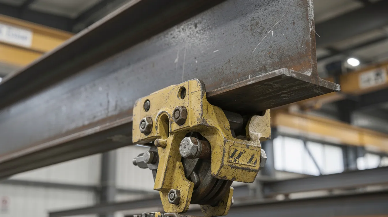
Connection hardware must transfer the full factored dynamic load from the hoist trolley into the supporting structure without yielding, slipping, or fatiguing. For steel I-beams, the simplest arrangement is a beam clamp that grips both flanges, allowing the trolley to roll along the monorail track. Where permanent installation is required, bolted or welded brackets with gusset plates distribute load into the web and flanges.
For concrete soffits, the choice between mechanical expansion anchors and chemical (adhesive) anchors affects both capacity and installation procedure. Mechanical anchors provide immediate load capacity and perform well in uncracked concrete. Chemical anchors, which bond a threaded rod into a drilled hole using epoxy or hybrid resin, offer higher tension capacity in overhead applications and better performance in cracked or variable-quality concrete, but require 12 to 24 hours of curing before loading. Hilti Singapore and similar providers offer on-site pull-out testing to verify actual anchor capacity in the host material; PEs often require these tests for older buildings with unknown concrete quality.
Anchor layouts must account for combined tension and shear. A hoist swinging its load generates horizontal shear at the anchor point simultaneously with vertical tension. The PE verifies that the interaction ratio (applied tension / tension capacity + applied shear / shear capacity) remains below 1.0 with appropriate safety factors.
Installation Procedures and Compliance Framework
Once the structural evaluation confirms adequate capacity, the installation follows a documented sequence that ends with PE certification specifying operating limits.
PE Certification Process
PE certification is required whenever the hoist installation introduces new loads to existing structural members. The process follows these steps:
-
Site survey and measurement: The PE or their engineering team visits the facility to measure beam sections, span lengths, connection details, and clearances. Existing load sources (MEP services, stored materials on mezzanines, equipment mounted to beams) are recorded. For concrete soffits, core samples or cover-meter scans establish material properties.
-
Load calculation and capacity check: Static loads from the hoist and maximum payload are combined with the SS 497 dynamic multiplier. The factored design load is compared against the structural capacity using SS EN 1993 for steel or SS CP 65 / SS EN 1992 for concrete. Deflection at serviceability limit state (typically limited to span/250 or span/300 for crane beams) is also verified.
-
Connection design and hardware specification: The PE specifies anchor type, size, embedment depth, spacing, and edge distances, or beam clamp ratings and trolley specifications. Base plates, stiffeners, and weld details are drawn where needed.
-
PE certification letter: The final deliverable is a signed and stamped letter stating the maximum safe working load, permissible hoisting speed, monorail track length and configuration, and required maintenance interval. This letter serves as the regulatory record for the installation.
Regulatory Compliance Comparison for Overhead Cranes
|
Scenario |
Minor Works (PE Endorsement) |
A&A Submission Required |
|---|---|---|
|
Load condition |
Hoist load within existing beam/slab capacity, no structural modification |
Hoist load exceeds capacity; new beams, strengthening, or foundation work needed |
|
Typical timeline |
2 to 4 weeks for PE review and certification |
8 to 16 weeks including BCA review and potential revisions |
|
Cost |
PE fee plus installation contractor |
Full structural consultant fee, drawing preparation, BCA submission fees, possible Accredited Checker fee |
|
Documentation |
PE calculation report and certification letter |
Full structural plans, PE endorsement, possible Accredited Checker review |
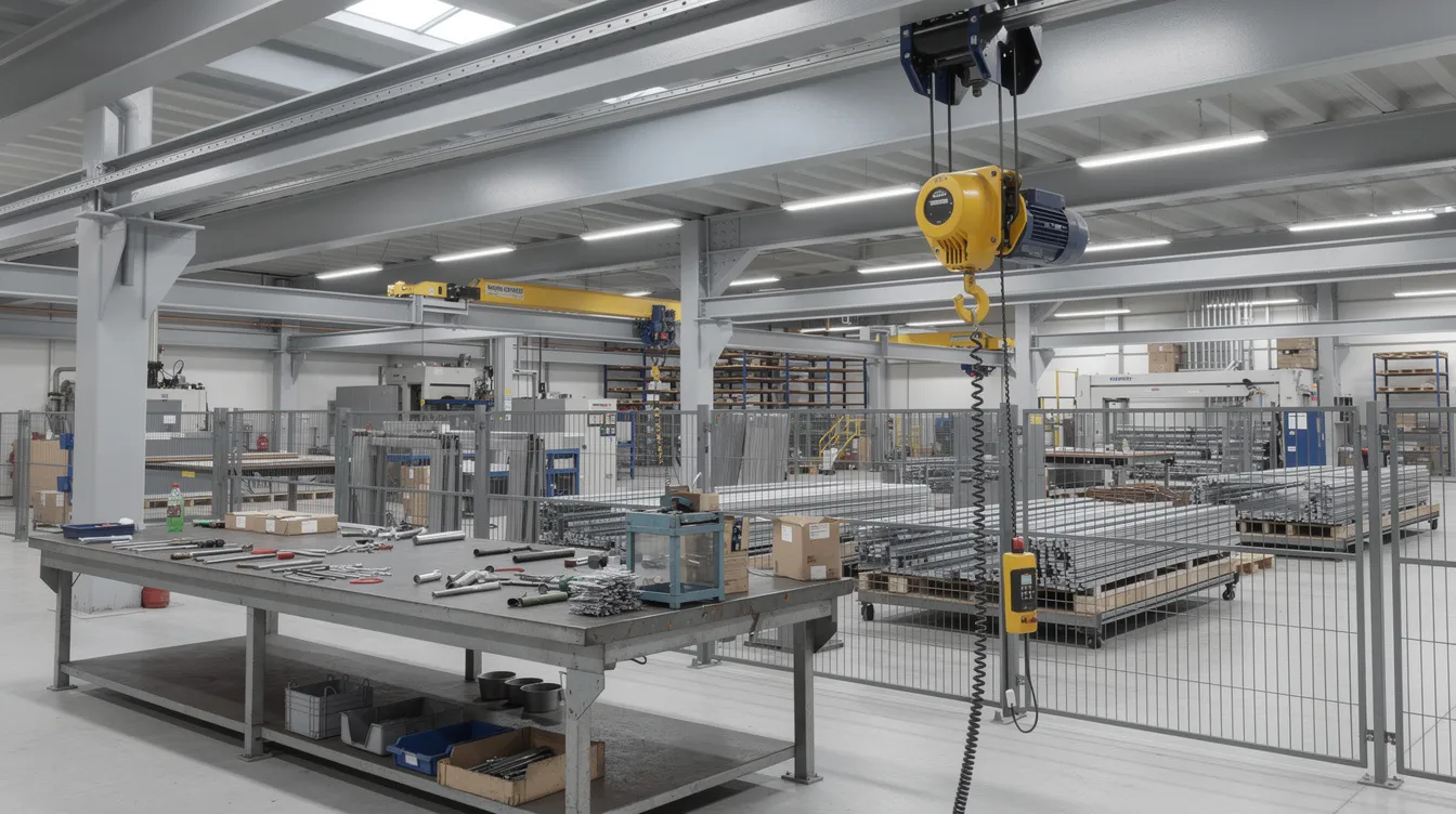
Facility managers should request a preliminary load assessment before committing to either pathway. A PE can determine within one to two site visits whether the existing structure supports the planned monorail crane system or whether strengthening is needed. Monorail cranes are a cost-effective alternative to bridge cranes and gantry cranes because they require less steel and can be installed without full-scale redesign of facilities. For confined, repetitive lifting tasks, workstation cranes may also be considered where a full monorail layout is not necessary. Monorail systems attach directly to existing overhead structures, and installation requires no full-scale redesign of facilities.
Common Challenges and Cost Effective Alternative Solutions
Three issues recur across light hoist installations in existing Singapore factory buildings. Each has established engineering responses.
Insufficient Existing Beam Capacity
When an existing I beam is already at 80% or higher utilization, adding even a small monorail hoist pushes it beyond code limits. The most common solution is installing a secondary monorail beam below the primary beam, supported at multiple points to distribute the hoist load across two or more primary members. This approach spreads the concentrated point load into distributed reactions. Alternatively, a load-distributing trolley run that spans between two parallel beams shares the hoist force equally between them. Both methods avoid modifying the primary structural members, keeping the installation within minor works scope. For heavier applications, a separate free-standing gantry crane bypasses the overhead structure entirely, though this occupies floor space.
Unknown Structural Details in Older Buildings
Many Singapore industrial buildings constructed in the 1970s and 1980s lack accessible as-built drawings. Without knowing the steel grade of a beam or the reinforcement in a concrete slab, the PE cannot calculate capacity. Non-destructive testing provides the necessary data: cover meters detect rebar location and size; rebound hammer tests estimate concrete compressive strength with ±15 to 20% accuracy; ultrasonic thickness gauges measure steel web and flange thickness through paint and corrosion layers. Where these methods leave uncertainty, PEs assume conservative values: S235 for unidentified steel, 20 MPa for unverified concrete, and minimum code reinforcement ratios. These assumptions reduce the calculated capacity, which sometimes triggers the need for strengthening that could be avoided with better data. Commissioning a structural survey with core sampling before design begins often pays for itself by confirming higher capacities and avoiding unnecessary reinforcement.
Space Constraints and Service Conflicts
Factory ceiling areas carry sprinkler pipes, cable trays, lighting, and ventilation ducts. A monorail track running through these services can obstruct sprinkler coverage (triggering SCDF fire safety concerns), damage cable insulation during trolley operation, or reduce headroom below code minimums. The PE coordinates with MEP consultants to route the monorail around obstructions. Enclosed track monorail systems with integrated trolley components have lower profiles than open I beam tracks, reducing vertical clearance requirements. Where ceiling-mounted tracks are impractical, wall-bracket-supported monorail beams or jib crane alternatives provide lifting at individual workstations without ceiling penetration.
Overhead monorail systems provide predictable load movement along a fixed track, which allows the PE to define exact load positions for structural analysis. Unlike a bridge crane that can place a load anywhere within its bay, a monorail follows a precise engineered route from point A to point B, making the structural assessment simpler and more conservative assumptions unnecessary. Monorails improve workflow by reducing transport time between workstations and reduce manual handling of heavy loads across larger areas. Monorail cranes can lift between 250 and 4,000 lbs, covering most light industrial capacities. They provide smooth and controlled load transport, are adaptable to unique facility layouts, and save valuable floor space by using the ceiling. Monorail cranes have lower maintenance needs due to fewer moving parts compared to bridge cranes.
Ceiling-mounted tracks keep workspaces clear of bulky lifting equipment. Monorail networks can integrate with several manufacturing cells, and monorails can follow complex layouts with curved tracks and switches. Monorail systems can navigate corners with curve track options and can be easily extended by adding track sections or switches. Monorail cranes provide two axes of hook movement: up/down and forward/back, making them effective in tight spaces and confined workstations.
Monorail systems optimize vertical space, freeing floor area for assembly lines, conveyor belts, and other production equipment. They are an economical solution for facilities that require limited lifting capacity and repetitive point-to-point transfers in production lines. Overhead monorail cranes run on a single stationary beam and handle heavier sustained capacities smoothly compared to manual handling. Light hoists are designed for vertical lifting and lowering and are better suited for occasional lifts at individual workstations, while monorail cranes serve operations where loads are repetitively moved between fixed stations. Monorail cranes are a cost-effective alternative to gantry cranes for production applications where a monorail configuration along straight sections or curved tracks meets the material handling requirements.
Conclusion and Next Steps
Light hoist installations under 1 tonne can proceed through PE endorsement as minor works when dynamic load analysis confirms the existing structure has adequate reserve capacity. The process depends on accurate field measurement, correct application of SS 497:2011 dynamic multipliers, and structural verification under SS EN 1993 or SS CP 65. When these conditions are met, facility managers avoid the 8 to 16 week timeline and higher costs of full A&A submissions.
To move forward with a monorail hoist installation:
-
Commission a structural survey of the proposed monorail track area, including beam measurements, material identification, and service mapping
-
Request preliminary load calculations from a PE to determine whether the existing structure supports the planned hoist capacity and speed
-
Obtain PE certification with specified load limits, operating parameters, and maintenance requirements before installation begins
For heavier lifting requirements, crane runway beam design involves additional fatigue analysis and may require dedicated support columns. Facilities planning expansion should also consider how monorail systems integrate with future production line layouts, as modular track sections allow the system to grow with operational needs.
Additional Resources
-
SS 497:2011 (Crane Machine standard): defines dynamic multiplier I₂ values for different application groups and hoisting speeds
-
SS EN 1993 (Structural steel design): steel member capacity checks including flexure, buckling, and connection design, applied with Singapore National Annex
-
SS CP 65: Part 1:1999: reinforced concrete design provisions for slab and beam capacity verification, anchor embedment, and breakout calculations
-
BCA Structural Plan Submission Guidelines: criteria for determining whether works qualify as minor/insignificant or require full plan submission (BCA submission page)
-
FEM Analysis for Complex Steel Structure Connections: detailed guidance on analyzing non-standard connection geometries for hoist brackets and base plates