
Introduction
Designing Earth Retaining and Stabilising Structures (ERSS) for sites near MRT tunnels in Singapore demands a rigorous, step-by-step application of SS EN Eurocodes – particularly SS EN 1997-1 and its Singapore National Annex – integrated with LTA’s railway protection requirements and BCA’s geotechnical building works framework. This article provides that structured workflow, guiding practitioners from ground investigation through ULS and SLS verification to construction monitoring, specifically for deep excavation projects within or adjacent to MRT Protection Zones.
The scope here is design methodology and regulatory compliance, not a software tutorial or finite element method (FEM) manual. The target audience includes Professional Engineers, geotechnical and structural engineers, contractors, and developers who are planning basement excavation or infrastructure works where existing MRT tunnels impose strict movement limits – often in the low single-digit millimetres.
In summary, the step-by-step flow proceeds as follows: define project geometry and tunnel proximity → execute ground investigation → select the Eurocode 7 Design Approach (DA1 per the Singapore National Annex) → develop ground and groundwater models → configure an ERSS scheme → apply ULS checks (stability, basal heave, hydraulic uplift) → verify SLS checks (wall deflection, ground settlement, tunnel deformation) → detail structural components → plan instrumentation and the observational method.
Key takeaways from this article:
-
How to align ERSS design tightly with SS EN 1997-1 and the Singapore National Annex partial factors for both Ultimate Limit State and Serviceability Limit State checks.
-
Why movement control near operating MRT tunnels requires settlement limits as strict as 15 mm total and differential settlement of 1:1000 – and how to design for them.
-
How to select the right retaining solution (diaphragm walls, secant pile walls, sheet piles) based on stiffness, water-tightness, and vibration constraints near tunnels.
-
The regulatory expectations of BCA and LTA, including dual submissions, PE(Geo) endorsement, independent checking, and the AAA monitoring system.
-
How AEC Technical Advisory typically structures these projects from concept to construction monitoring.
Understanding ERSS Design Near MRT Tunnels
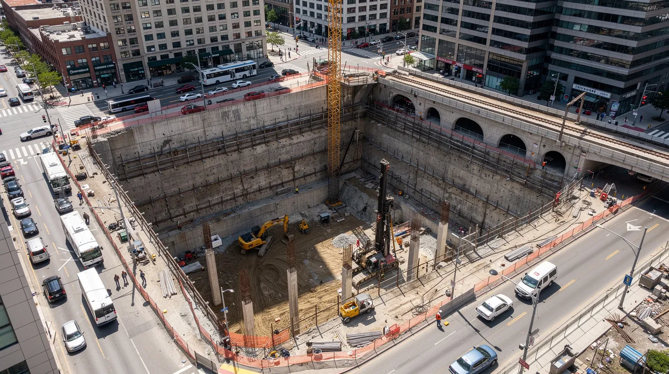
ERSS and geotechnical design near MRT tunnels is fundamentally more demanding than standalone basement works. An operating tunnel introduces an existing, deformation-sensitive structure into the influence zone of new excavation, meaning that every millimetre of wall movement, every change in pore water pressure, and every load transfer through the soil mass has consequences for tunnel lining integrity and track alignment. The design must simultaneously satisfy the structural capacity of the retaining wall, the geotechnical stability of the excavation, and the strict displacement criteria imposed to protect MRT infrastructure.
What Are ERSS in the Context of MRT Tunnel Protection?
Earth retaining and stabilising structures encompass the full suite of wall systems and support elements used to enable deep excavation while controlling lateral soil and water movement. In the MRT tunnel context, ERSS includes diaphragm walls, secant piles, contiguous bored piles, steel sheet piles, soldier piles, ground anchors, soil nails, and soil improvement techniques such as jet grouting or deep soil mixing. ERSS also includes diaphragm walls, sheet piles, and soldier piles as defined under Singapore’s regulatory framework. Designing Earth Retaining or Stabilising Structures near MRT infrastructure follows SS EN 1997 and LTA guidelines.
These stabilizing structures function as the primary continuous barrier controlling lateral earth pressure and groundwater inflow around operating tunnels. In Singapore, typical MRT-adjacent applications include cut-and-cover station boxes being deepened or extended, crossover caverns, deep basement tie-ins above or adjacent to bored tunnels, and underpasses crossing over existing tunnel alignments.
A critical principle: for MRT-protected corridors, even nominally temporary ERSS must be treated as safety-critical permanent structures. Any soil or water movement during the service life of even a temporary excavation support system can permanently deform tunnel linings, misalign tracks, or open tunnel joints. The Nicoll Highway collapse in 2004 killed four workers due to geotechnical failure, starkly demonstrating what happens when earth retaining systems near transit infrastructure are not designed and monitored to the highest standards.
Key Geotechnical Risks Near Operating MRT Tunnels
The principal geotechnical risks near operating MRT tunnels include:
-
Differential settlement causing tunnel ovalisation (change in cross-section), track misalignment, joint opening, or lining leakage. MRT tunnels require strict displacement criteria to avoid excessive distortion or settlement.
-
Excessive lateral displacement of the ERSS wall or surrounding soil mass, which can impose structural loads on tunnel linings or deform neighboring structures.
-
Basal instability and toe heave, especially where the excavation base is shallow relative to the tunnel invert or where groundwater pressure is high. Basal heave can lead to total collapse of excavation walls.
-
Hydraulic uplift and piping, which can cause soil loss and sinkholes during excavations, particularly affecting tunnel inverts.
-
Vibration impacts during piling or anchor installation methods that risk dynamic loading on tunnel integrity and serviceability.
Excavation-induced movements and stress redistribution must be carefully analyzed to prevent tunnel distortion. These risks are tightly coupled: wall deflection induces a settlement trough above the tunnel crown; groundwater drawdown causes consolidation settlement outside the excavation; dewatering or seepage influences pore pressures beneath the tunnel invert, increasing both settlement and uplift risk.
Quantitatively, LTA’s Civil Design Criteria specify that total allowable movement for existing MRT tunnels is strictly limited to 15 mm in any direction, and differential settlement must not exceed 1:1000 in any plane. Track geometry distortions are even more granular: vertical dip is limited to 5 mm over a 5 m chord, and twist or cant change is limited to 1.5 mm over a 2.5 m chord. These are far tighter than typical allowable settlement criteria for ordinary buildings or heritage buildings, underscoring why these projects demand specialised geotechnical design.
These risks are managed through a structured SS EN 1997 design and verification process – the subject of the remaining sections.
How SS EN Eurocodes Frame Geotechnical Design in Singapore
Singapore adopted Eurocode standards in stages starting from 2010, replacing previous British Standards with the SS EN framework. For geotechnical design, the key codes are:
-
SS EN 1990 – Basis of structural design, defining consequence classes, combinations of actions, and the limit state philosophy.
-
SS EN 1991 – Actions on structures (loads, surcharges, environmental effects).
-
SS EN 1992 / SS EN 1993 – Structural design of reinforced concrete and steel structures, applicable to diaphragm walls, walers, struts, and anchors.
-
SS EN 1997-1 – Geotechnical design, the core reference for ERSS, with the Singapore National Annex specifying locally applicable partial factors and Design Approaches.
Eurocode 7 governs geotechnical design in Singapore, replacing the “single global factor of safety” approach with limit state design: Ultimate Limit State (ULS) checks address catastrophic outcomes in ERSS design, while Serviceability Limit State checks limit wall deflection and ground settlement. This framework is crucial when dealing with very small acceptable deformations near tunnels. Eurocode 7 applies partial factors to manage geotechnical uncertainty, and the Singapore National Annex customizes Eurocode standards for local conditions – including mandating Design Approach 1 (DA1) for STR and GEO limit states.
The following section sets out the specific regulatory and code requirements that govern sites within MRT Protection Zones.
Regulatory and Code Framework for Sites Near MRT Tunnels
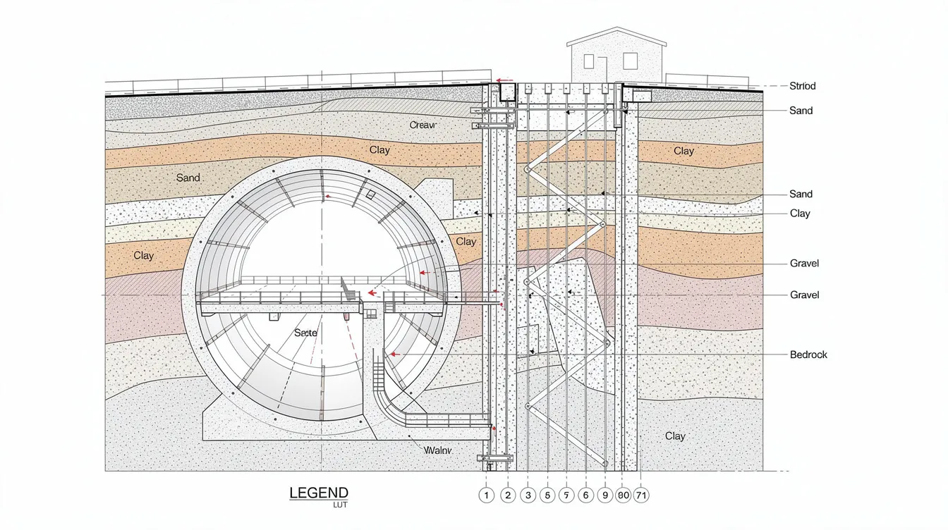
Before entering the step-by-step design process, practitioners must understand the regulatory landscape that shapes every MRT-adjacent ERSS project. The interplay between BCA’s building works framework and LTA’s railway protection requirements creates a dual-submission environment with stringent documentation and monitoring expectations.
Singapore Regulatory Context: BCA, LTA and MRT Protection Zones
The Rapid Transit Systems (Railway Protection, Restricted Activities) Regulations define the Railway Protection Zone (RPZ) as land within 40 m from the outermost edge of any MRT railway structure – on, above, or below ground. Any regulated or restricted activity within this zone requires LTA’s permission and must comply with conditions set out in the Code of Practice for Railway Protection (2024 edition, with a September 2026 addendum addressing compressible soil zones). LTA imposes additional controls within Railway Protection Zones beyond standard BCA requirements.
The Building and Construction Authority (BCA) regulates excavation works deeper than 6 meters, requiring formal ERSS submissions with PE(Geo) endorsement. BCA mandates a two-set-of-eyes principle for ERSS projects, meaning an independent checker (ICE) or accredited checker must review the design. Geotechnical work near MRT tunnels classified under Geotechnical Category 2 or 3 requires comprehensive evaluations. Excavations near MRT tunnels may require dual submissions to the Building and Construction Authority and LTA.
LTA often imposes more stringent movement and vibration limits than BCA for works near operational tunnels, including heightened instrumentation density and real-time monitoring.
Relevant SS EN Parts for MRT-Adjacent ERSS Design
The key standards and their roles in ERSS and tunnel-interface design are:
-
SS EN 1990 – Defines consequence classes (CC2/CC3 typical for MRT-adjacent works), reliability requirements, and combinations of actions.
-
SS EN 1991 – Specifies characteristic loads: earth pressures, water pressures, traffic surcharges, construction loads, and thermal loads.
-
SS EN 1992 – Governs reinforced concrete structural design of diaphragm walls, slabs, and walers, including crack control and watertightness.
-
SS EN 1993 – Governs steel structures: struts, walers, steel sheet piles, and temporary steel structures.
-
SS EN 1997-1 (with Singapore National Annex) – The core geotechnical code; clauses covering retaining structures, piled walls, deep excavation stability, and the derivation of characteristic soil parameters. Eurocode 7 includes three design approaches for geotechnical design, but the national annex mandates DA1 for STR/GEO limit states.
Partial factors must be applied to actions and material properties in the geotechnical design process. Under the Singapore National Annex, soil strength parameters receive specific factors: angle of shearing resistance φ′ is factored at γ_M = 1.25, effective cohesion c′ at 1.25, and undrained shear strength c_u at 1.40 under ULS. Structural members – diaphragm walls as reinforced concrete, walers as steel, anchors, and slabs – must satisfy both geotechnical and structural Eurocode checks.
LTA / BCA Expectations for Design Documentation and Monitoring
Core deliverables for MRT-adjacent ERSS projects include:
-
Design Basis Report explicitly referencing SS EN 1997-1, the Singapore National Annex, and LTA tunnel protection criteria.
-
Ground Investigation Report with soil and rock profiles established through comprehensive geotechnical investigations.
-
Risk Assessment for tunnel impacts, covering all excavation stages and construction sequence.
-
Detailed ERSS calculations under ULS (DA1 combinations) and SLS, with clear documentation of partial factors, characteristic values, and load paths.
-
Instrumentation and monitoring plan specifying instrument types, locations, reading frequency, and trigger levels.
-
Contingency and observational method procedures, including predefined “if–then” actions for approaching movement limits.
Submissions must include site investigation reports and design calculations. Typical ERSS submission timelines range from 3 to 6 weeks. BCA mandates a three-tier monitoring system for critical parameters, formalised as the AAA (Alert–Alarm–Action) trigger system. The AAA monitoring system triggers immediate work suspension if limits are breached. The observational method may be adopted following BCA’s framework, but both the standard design and the OM approach must be documented for approval.
The following sections show how AEC Technical Advisory structures a step-by-step Eurocode-compliant design around these regulatory requirements.
Step-by-Step Approach to SS EN 1997 Geotechnical Design Near MRT Tunnels
This is the core “how-to” section, mirroring the real project sequence used by AEC Technical Advisory for MRT-adjacent ERSS and geotechnical design. Each step builds on the previous, forming a traceable design chain from feasibility through detailed design and into construction.
Step 1 – Define Project Geometry, Tunnel Proximity, and Performance Requirements
Begin by establishing the 3D geometry of the proposed works: excavation footprint, basement levels, excavation depth, and the spatial relationship to the MRT tunnel alignment in both plan and elevation. Identify the clearance between the proposed excavation base and the tunnel crown, between foundation elements and the tunnel springline, and between any piling and the tunnel extrados.
Classify the project consequence class (typically CC2 or CC3 per SS EN 1990) and assign performance criteria. These include maximum tunnel settlement, maximum rotation and track level change, allowable building settlement for neighboring structures, and wall deflection limits. Total allowable movement for existing MRT tunnels is strictly limited to 15 mm in any direction, with differential settlement of 1:1000 and track geometry distortions as described above.
Early coordination with LTA to obtain as-built tunnel alignment drawings, lining type, and stiffness assumptions is critical. Without accurate tunnel data, the entire design rests on uncertain foundations.
Step 2 – Plan and Execute Ground Investigation to Support SS EN 1997 Design
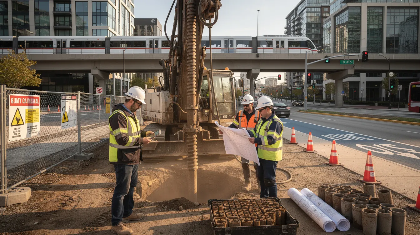
Ground investigations must characterize subsurface geology to inform design and safety assessments. The typical investigation scope near tunnels includes:
-
Boreholes extending at least 5 m below the tunnel invert, positioned to characterise critical slip surfaces and load paths to the tunnel.
-
In-situ tests: SPT, CPTu (especially useful in marine clay and soft clay profiles), and pressuremeter tests for stiffness characterisation.
-
Laboratory tests: oedometer (consolidation), triaxial (effective and total stress), and permeability tests.
-
Installation of standpipe and vibrating-wire piezometers to establish groundwater levels and monitor pore water pressures.
Soil and rock profiles must be established through comprehensive geotechnical investigations. Ground and groundwater conditions must be understood in full, particularly in areas of reclaimed land or where fill overlies marine clay – conditions common throughout much of Singapore’s development footprint.
GI results are interpreted into a stratified ground model with characteristic soil parameters (c_k, φ_k, E_u, c_u, permeability k) derived in accordance with SS EN 1997-1 clause 2.4.5.2 and BCA’s Guide on Ground Investigation and Geotechnical Characteristic Values. For large soil volumes and global failures, mean values at 95% confidence are used; for local failures or smaller soil volumes, the 5% fractile applies. A thorough understanding of geotechnical investigations is essential at this stage.
Step 3 – Establish Design Situations and Select Eurocode 7 Design Approach
Define persistent, transient, and accidental design situations per SS EN 1990 and SS EN 1997. Typical situations for MRT-adjacent ERSS include:
-
Persistent: normal excavation stages at full depth with all strut levels installed.
-
Transient: intermediate excavation stages as excavation proceeds, partial dewatering conditions, construction surcharges.
-
Accidental: temporary loss of a strut level, accidental surcharge near the tunnel, flooding of the excavation.
Strict compliance with Eurocode 7 and local LTA requirements is necessary for safe MRT tunneling projects. Under the Singapore National Annex, Design Approach 1 (DA1) is mandated for STR and GEO limit states. DA1 requires checking two combinations:
-
Combination 1: partial factors primarily on actions (γ_F applied), with soil parameters at characteristic values.
-
Combination 2: partial factors primarily on soil strength parameters (γ_M applied), with actions closer to characteristic values.
For each design situation, tabulate which partial factors apply to actions, soil parameters, and resistances, clearly identifying which DA combination governs. In MRT-adjacent cases, tunnel-related mechanisms (deep-seated failure, basal heave passing beneath the tunnel) may govern which combination is more critical.
Step 4 – Develop the Ground and Groundwater Model
Construct a 2D or 3D conceptual ground profile showing soil layers, rockhead, fill, reclaimed strata, and the tunnel position relative to these layers. The model should capture:
-
Layer-by-layer soil mechanics properties including stiffness, soil strength, and permeability.
-
Characteristic groundwater levels, possible artesian conditions in deeper strata, and potential drawdown due to pumping.
-
The position of the tunnel within the soil profile – whether it sits in soft clay, the Old Alluvium, or transitional zones.
Groundwater management is crucial in minimizing consolidation settlement affecting nearby MRT tunnels. Perform sensitivity checks for groundwater scenarios that most affect tunnel uplift, piping, and settlement predictions – for example, varying the drawdown depth by ±1–2 m to understand its impact on effective stress changes beneath the tunnel invert.
Consistency with SS EN 1997 hydrostatic and seepage assumptions is essential. Where artesian pressures exist, the model must account for hydraulic uplift forces on the excavation base and their effect on tunnel stability.
Step 5 – Select and Configure an ERSS Scheme Compatible with Tunnel Protection
Screen wall types against stiffness, water-tightness, vibration limits, and constructability close to tunnels:
-
Diaphragm walls are preferred for very deep excavations (diaphragm walls can reach depths of 20–40 m in Singapore) with high wall stiffness, excellent water-tightness, and low vibration during diaphragm wall construction. They form a continuous barrier and are well-suited for permanent structures.
-
Secant pile walls offer moderate stiffness and are individually constructed; useful where site geometry precludes panel excavation, though less continuous and potentially more permeable at joints.
-
Contiguous bored piles (tangent pile walls with gaps) are suitable for moderate excavation depth with lower groundwater, and contiguous bored piles typically have diameters ranging from 600 to 1,200 mm.
-
Steel sheet piles are suitable for excavation depths of 4–10 m but have lower wall stiffness and can generate significant vibration if driven. Sheet pile walls are generally unsuitable for close proximity to operating tunnels unless installed by press-in methods.
Configure the internal support systems: internal struts, walers, intermediate slabs (for top-down construction), or ground anchors, with emphasis on controlling wall deflection and limiting load transfer to the tunnel. Top-down construction allows earlier superstructure commencement while providing early slab bracing that reduces wall movement and ground deformation – a significant advantage near MRT tunnels.
Ground improvement techniques such as jet grouting or deep soil mixing may be needed at the excavation base to reduce toe heave and improve passive resistance, but ground improvement techniques must be cautiously assessed to prevent adverse effects on MRT tunnels.
For detailed guidance on selecting the right retaining solution, understanding the full range of retaining systems available in Singapore’s geological context is essential.
Step 6 – Define Actions, Load Combinations, and Surcharges
Prepare a comprehensive action register for each excavation stage. Key actions include:
-
Earth pressures: active and at-rest pressures from the retained soil mass, computed using soil strength parameters factored per DA1.
-
Water pressures: hydrostatic and seepage-induced pressures, treated as permanent actions.
-
Construction loads: crane pads, material stockpiles, construction traffic surcharges.
-
Existing foundations: loads from adjacent buildings and their existing foundations, including any heritage buildings near the site.
-
Tunnel overburden stress changes: the stress relief and redistribution caused by removing soil above and beside the tunnel.
-
Thermal loads: temperature effects on struts and slabs, which can significantly alter strut loads in exposed conditions.
For each excavation stage, indicate whether each load is geotechnical or structural (for DA treatment) and how partial factors are applied. Tunnel loads and stiffness effects must be modelled carefully in the same combinations, avoiding “double counting” or omission of interaction effects.
Step 7 – Perform ULS Checks for Stability and Tunnel Safety
Apply DA1 Combinations 1 and 2 to verify:
-
Wall overturning, sliding, and toe stability: confirm that passive resistance below the excavation base is adequate, with wall embedment into competent strata (often Old Alluvium in Singapore).
-
Basal heave and deep-seated failure: check stability against failure surfaces that pass through or beneath the tunnel. Diaphragm walls outperform sheet piles in factor of safety for basal heave due to their greater embedment and stiffness.
-
Hydraulic uplift and piping: verify that the excavation base is safe against uplift from groundwater pressure, particularly where the tunnel invert is close. Hydraulic uplift can cause soil loss and sinkholes during excavations.
Ultimate Limit State checks address catastrophic outcomes in ERSS design. In MRT-adjacent cases, global stability analyses – for example, slip circles that pass through or below the tunnel – often govern wall embedment depth and may drive the need for ground improvement or deeper wall sockets.
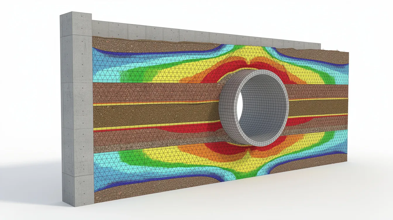
Design outputs should directly show safety margins for tunnel-related mechanisms, not only for the excavation box. The use of advanced numerical modelling is recommended for assessing soil-structure interactions adjacent to MRT tunnels, particularly numerical modeling using finite element methods for complex geometries. Numerical modelling helps capture soil-wall-tunnel interaction that simplified methods may miss.
Step 8 – Perform SLS Checks for Deformation and Tunnel Movement Limits
Serviceability Limit State assessments prioritize ground deformation and structural movement near MRT tunnels. SS EN 1997’s limit state philosophy requires explicit SLS verification of:
-
Wall deflection profiles at each excavation stage as excavation proceeds.
-
Ground settlement troughs behind the wall and above the tunnel crown.
-
Tunnel lining deformation – ovalisation, vertical and horizontal displacement.
-
Joint opening between tunnel segments.
Compare predicted tunnel settlement and distortion against LTA and track alignment criteria. The LTA enforces strict allowable movement limits for existing MRT tunnels during construction activities. Ground settlement limits are often set to millimetres near sensitive structures. ERSS must limit ground deformation to millimeters near sensitive structures.
Where movements must be kept within a few millimetres, FEM or advanced soil-structure interaction modelling (e.g., using PLAXIS or similar software) is essential. Iterate ERSS stiffness – wall thickness, wall bending capacity, embedment depth, support spacing, top-down slabs, soil improvement – until all deformation criteria are met.
This iterative process is where temporary ERSS and permanent ERSS configurations often converge: the stiffness required for serviceability near tunnels may dictate a wall system that is effectively permanent in its robustness.
Step 9 – Detail Structural Components to Eurocodes
With internal forces from the geotechnical analysis confirmed, design all structural components:
-
Diaphragm walls: reinforcement cage design for wall bending, shear, and axial loads per SS EN 1992. Crack control and watertightness are critical for walls forming part of the permanent basement envelope, especially where they are close to the tunnel.
-
Struts and walers: structural design per SS EN 1993 for axial load, buckling, and connection details. Include thermal loads in strut design.
-
Ground anchors: design for tensile capacity, corrosion protection (especially for permanent anchors), and pullout resistance in the soil.
-
Slabs: intermediate slabs and base slabs designed for both temporary excavation support loads and permanent structural loads.
Document load paths from soil → ERSS → permanent structure → foundation, ensuring consistency between geotechnical and structural checks. Special detailing near MRT tunnels includes fire considerations where tunnels may be affected by fire scenarios, and structural capacity verification under all excavation stages.
For further guidance on structural design of ERSS in MRT construction, understanding the interaction between temporary works and permanent structures is essential.
Step 10 – Plan Instrumentation, Observational Method, and Construction Sequence
Instrumentation and monitoring plans must be developed to track construction impacts on MRT infrastructure. The instrumentation suite for MRT-adjacent excavations typically includes:
-
Inclinometers installed in the retaining wall and in the ground behind it. Inclinometers measure wall deflection during excavation processes.
-
Settlement markers on adjacent roads, buildings, and along the tunnel alignment. Settlement markers detect vertical ground settlement on adjacent structures.
-
Piezometers (vibrating-wire or standpipe) to monitor groundwater and pore water pressure. Piezometers monitor pore water pressure in excavations.
-
Strut load cells to verify actual strut forces against design predictions.
-
Tunnel convergence pins and tiltmeters inside the tunnel to track lining deformation and track geometry.
-
Vibration monitors during piling or other dynamic activities.
BCA mandates a three-tier monitoring system for critical parameters, structured as Alert–Alarm–Action (AAA) thresholds. The observational method – an SS EN 1997 principle – is adapted for MRT-adjacent projects with predefined actions for approaching trigger levels. These may include reducing excavation advance rates, installing additional struts, activating recharge wells, or initiating compensation grouting.
The construction sequence – including staged excavation, support installation, preloading, and dewatering – must be documented in method statements submitted to both LTA and BCA. For a detailed walkthrough of LTA impact assessment requirements, early engagement is essential.
Comparing Key ERSS Options for MRT-Adjacent Sites
Expanding on Step 5, this section provides a direct comparative analysis of the principal wall systems used near MRT tunnels, evaluated against the criteria that matter most under SS EN design and LTA protection requirements.
Comparative Performance Under SS EN Design Criteria
|
Criterion |
Diaphragm Wall |
Secant Pile Wall |
Sheet Pile Wall |
|---|---|---|---|
|
Wall stiffness / movement control |
Very high; preferred for very deep excavations and tight movement limits |
Moderate to high; depends on pile overlap and diameter |
Lower; limited by section modulus |
|
Water-tightness |
Excellent; forms continuous barrier |
Good if well-constructed overlap; joints can leak |
Fair; interlocks may leak, especially at depth |
|
Vibration impact on tunnels |
Very low (slurry trench construction method) |
Low (bored) |
High if driven; low if pressed-in |
|
Constructability in tight sites |
Requires panel equipment and guide walls; moderate footprint |
Flexible positioning; smaller equipment possible |
Quick mobilisation; limited depth |
|
Top-down integration |
Excellent; wall acts as permanent structure |
Good; can serve as permanent wall |
Poor; typically temporary works only |
|
Applicable depth range |
20–40 m (can reach depths of 20–40 meters in Singapore) |
10–25 m typical |
4–10 m typical (steel sheet piles are suitable for excavation depths of 4–10 m) |
|
Relative cost |
Higher |
Moderate |
Lower |
AEC Technical Advisory typically recommends:
-
Diaphragm walls for sites in very close proximity to operating tunnels, where wall stiffness must be maximised and the wall will serve as both temporary ERSS and permanent ERSS. Their superior performance in basal heave resistance and watertightness makes them the default for deep basement projects near bored MRT tunnels.
-
Secant pile walls for moderate proximity with high groundwater, where diaphragm wall construction is constrained by site access or geometry.
-
Sheet piles (press-in method only) for shallow excavations at greater distance from tunnels, where vibration is highly restricted but excavation depth is modest.
Other retaining systems – including soldier piles with lagging, or combinations of soil nailing and ground anchors – may be considered for specific geometries, but rarely meet the stringent movement control and water-tightness requirements of MRT-adjacent sites.
The “best” system always depends on ground conditions, tunnel sensitivity, and the Eurocode design outputs from Steps 7 and 8.
Common Challenges and Solutions in MRT-Adjacent ERSS Projects
Even with a robust Eurocode-based design, execution challenges can compromise tunnel safety if not managed. The following practical problems arise frequently and require proactive mitigation grounded in SS EN and regulatory context.
Challenge 1 – Limited Clearance Above and Beside MRT Tunnels
When the excavation base or foundation piles are only a few metres above the tunnel crown or beside the tunnel springline, the margin for error effectively vanishes. Every increment of ground movement translates almost directly into tunnel displacement.
Solutions: Adopt stricter SLS criteria than the code minimum. Use top-down construction to provide early slab bracing. Specify local soil improvement (jet grouting, deep mixing) to stiffen the zone between the excavation base and the tunnel crown, increasing passive resistance. Where necessary, reduce the basement excavation depth near the tunnel and use transfer structures to span over the sensitive zone. Employ high-stiffness diaphragm walls with deep embedment.
Challenge 2 – Vibration and Noise Constraints for Operating Lines
Pile driving and other dynamic installation methods near tunnels and stations can generate peak particle velocities (PPV) that exceed LTA’s strict limits, risking damage to tunnel linings and disruption to train operations.
Solutions: Use bored piles or diaphragm walls rather than driven sheet piles. Where sheet piles are necessary, use hydraulic press-in methods that eliminate impact vibration. Stage works with real-time vibration monitoring. Coordinate with LTA for temporary speed restrictions during particularly sensitive construction activities if needed. Select installation methods that are inherently low-vibration.
Challenge 3 – Groundwater Control Without Inducing Excessive Tunnel Settlement
Aggressive dewatering lowers pore pressures around the tunnel, increasing effective stress in soft clay and compressible soils, and driving consolidation settlement. Groundwater management is crucial in minimizing consolidation settlement affecting nearby MRT tunnels.
Solutions: Design cut-off walls (secant piles or diaphragm walls) to form an effective groundwater barrier around the excavation. Install recharge wells on the tunnel side to maintain pore pressures. Implement staged pumping with continuous piezometer monitoring. Where feasible, design slabs and walls for higher water pressures rather than relying on heavy drawdown – accepting higher structural costs to protect the tunnel.
Challenge 4 – Programme Pressure vs. Observational Method Discipline
Compressed construction schedules create pressure to proceed quickly through excavation stages, but movement limits near MRT tunnels may require pauses or adjustments. The conflict between programme and safety is one of the most common sources of risk.
Solutions: Establish pre-agreed “if–then” action plans so that all parties – contractor, designer, LTA, BCA – know the response protocol before triggers are reached. Deploy digital dashboards (the emerging concept of a geotechnical digital twin) for real-time data accessible to all stakeholders. Build contingency allowances into the construction programme. Ensure contractual recognition that safety-driven pauses are anticipated, not exceptional.
Conclusion and Next Steps
Safe ERSS and geotechnical design near MRT tunnels in Singapore requires a Eurocode-based, step-by-step workflow that integrates high-quality ground models, rigorous ULS and SLS verification under SS EN 1997-1 and the Singapore National Annex, and tightly integrated monitoring and construction control. The consequences of inadequate design are severe – from millimetre-level track misalignment affecting train operations to catastrophic ground failure. Every stage, from ground investigation through to the final excavation lift, must be designed, checked, and monitored with the awareness that an operating transit system lies within the zone of influence.
Immediate next steps for practitioners:
-
Map whether your site intersects MRT Protection Zones – request railway protection plans from LTA and confirm clearances to tunnel alignment in 3D.
-
Commission or review ground investigations with tunnel constraints in mind – ensure boreholes extend below the tunnel invert and that in-situ and lab testing support derivation of characteristic soil parameters to SS EN 1997.
-
Prepare a design basis statement explicitly referencing SS EN 1997-1, the Singapore National Annex, and LTA’s Code of Practice for Railway Protection.
-
Engage a PE(Geo) and specialist advisory early – concept-stage engagement shapes footprint, depth, and the structural scheme around tunnel constraints, avoiding costly late redesign and authority pushback.
-
Develop your instrumentation and monitoring plan in parallel with design, not as an afterthought – trigger levels must be consistent with design predictions.
Related topics readers may explore next include detailed use of FEM for tunnel–excavation interaction, compensation grouting design for settlement mitigation, long-term settlement monitoring strategies, and the evolving requirements under LTA’s 2026 addendum for compressible soil zones.
Additional Resources and How AEC Technical Advisory Supports MRT-Adjacent Projects
Key Standards and Local Guidance
-
SS EN 1990 – Basis of structural design; used to define consequence classes and action combinations for MRT-adjacent works.
-
SS EN 1991 – Actions on structures; used to define characteristic loads including earth pressures, water pressures, and surcharges.
-
SS EN 1992 – Structural design of concrete; used for diaphragm wall reinforcement cage detailing, crack control, and slab design.
-
SS EN 1993 – Structural design of steel; used for strut, waler, and steel sheet pile design.
-
SS EN 1997-1 (with Singapore National Annex) – Geotechnical design; used to set partial factors, Design Approach, and characteristic value derivation for ERSS design near tunnels.
-
BCA Guide on Ground Investigation and Geotechnical Characteristic Values to EC7 – Used to derive statistically robust characteristic soil parameters.
-
BCA Code of Practice for ERSS (TR43) – Regulatory framework for ERSS submissions, checking, and monitoring.
-
LTA Code of Practice for Railway Protection (2024, with 2026 addendum) – Specifies movement limits, instrumentation, and submission requirements for works within RPZ.
-
LTA Civil Design Criteria – Settlement and track geometry limits for railway structures.
AEC Technical Advisory’s Role in Tunnel-Adjacent ERSS Design
AEC Technical Advisory provides specialist services for MRT-adjacent ERSS and geotechnical design projects, including:
-
Concept and detailed ERSS and foundation design under SS EN 1997 for near-MRT sites, from wall type selection through to reinforcement detailing.
-
Integrated geotechnical–structural modelling of tunnel–excavation interaction using 2D and 3D FEM approaches to predict and control ground movement.
-
BCA and LTA submissions, including PE endorsements, design basis reports, and technical responses to authority queries. Typical deep excavation approval workflows are managed end-to-end.
-
Instrumentation specification, data interpretation, and observational-method support during construction – including establishment of AAA trigger systems and real-time monitoring review using geotechnical instrumentation.
-
Independent checking and accredited checker roles for retaining structures requiring third-party verification.
Frequently Asked Questions on ERSS and Geotechnical Design Near MRT Tunnels
These frequently asked questions address common queries from developers, contractors, and engineers planning works close to MRT infrastructure.
When is an ERSS design under SS EN 1997 mandatory for sites near MRT tunnels?
BCA regulates excavations deeper than 6 meters in Singapore, requiring formal ERSS submissions with PE(Geo) endorsement. Within the MRT Railway Protection Zone (40 m from the outermost edge of any MRT structure), LTA imposes additional requirements regardless of excavation depth if the works could affect the tunnel envelope. Any excavation within the influence zone of an MRT tunnel – even if shallower than 6 m – will typically require ERSS design, submission, and independent checking. Excavations deeper than 6 meters require formal ERSS submissions in Singapore.
How do Eurocode design approaches (DA1 vs DA3) affect ERSS design for MRT-adjacent works?
Under the Singapore National Annex, DA1 is mandated for STR and GEO limit states. DA1 Combination 1 applies higher partial factors to actions while keeping soil parameters at characteristic values; Combination 2 applies partial factors to soil strength parameters while reducing action factors. For tunnel-related mechanisms – particularly deep-seated failure surfaces passing beneath the tunnel – Combination 2 often governs because reduced soil strength produces larger predicted deformations and lower stability margins. The designer must check both combinations and identify which is critical for each failure mechanism.
What level of movement control is typically required to protect operating MRT tunnels?
Total allowable movement for existing MRT tunnels is strictly limited to 15 mm in any direction, with differential settlement not exceeding 1:1000. Track geometry distortions are limited to 5 mm vertical dip over a 5 m chord and 1.5 mm twist over a 2.5 m chord. In practice, movement control targets in design are often set even tighter than these code limits to provide an adequate margin, particularly in soft clay or marine clay profiles where ground deformation is difficult to predict precisely. Actual criteria are set by LTA on a project-specific basis.
Can top-down construction significantly reduce impacts on MRT tunnels?
Yes. Top-down construction provides early slab propping at the ground level and intermediate slab levels, significantly increasing the effective wall stiffness and reducing wall deflection before the full excavation depth is reached. This construction method reduces open excavation time, limits the settlement trough, and provides greater movement control. It is a frequently recommended approach for deep basement projects within MRT Protection Zones where the construction sequence must minimise cumulative ground movement.
At what stage should AEC Technical Advisory or a PE(Geo) be engaged?
Engagement during the feasibility or concept design stage is strongly recommended. At this stage, the project footprint, basement depth, and structural scheme can be shaped around tunnel constraints – avoiding late redesign, authority pushback, and costly programme delays. Early PE(Geo) involvement ensures that ground investigation is scoped correctly, that preliminary ERSS options are evaluated against tunnel sensitivity, and that the design basis aligns with both BCA and LTA requirements from the outset.