
Introduction
Civil engineering design for slope stabilisation step by step approach to SS EN Eurocodes begins with understanding that every compliant slope design in Singapore follows a disciplined, sequential workflow anchored in Eurocode 7 (EN 1997) as locally adopted through SS EN standards and the Singapore National Annex. This article lays out that practical sequence-from ground investigation through limit state verification to construction monitoring-so that engineers, infrastructure owners, and authority reviewers can execute or evaluate slope stabilization projects with confidence.
The target readers are civil and geotechnical engineers working on roads, rail corridors, cut-and-fill platforms, and hillside developments across Singapore and ASEAN, as well as contractors preparing submissions and asset owners commissioning civil engineering works. Whether you are designing a 10 m highway cutting for LTA or stabilising a steep slope behind existing buildings, the framework described here applies. Civil engineering design for slope stabilization follows Eurocodes and local standards, and this article shows exactly how.
A compliant design under SS EN Eurocodes follows this practical sequence: rigorous ground investigation → realistic ground model → selection of characteristic values → limit state checks under SS EN 1997-1 using the correct Design Approach and partial factors → detailing of stabilisation systems and drainage → monitoring and authority submissions.
By working through this article you will gain:
-
A clear understanding of the Eurocode 7 / SS EN framework and how it governs slope stability analysis in Singapore
-
Practical guidance on structuring slope stability calculations using partial factors instead of a single global factor of safety
-
Knowledge of how to choose the correct design approach (DA1 Combination 1 and 2) and apply Singapore National Annex values
-
A step-by-step workflow for documenting geotechnical design and preparing authority submissions to BCA, LTA, and PUB
-
Awareness of how AEC Technical Advisory typically supports such projects from feasibility through construction monitoring
Understanding code-based slope stabilisation design
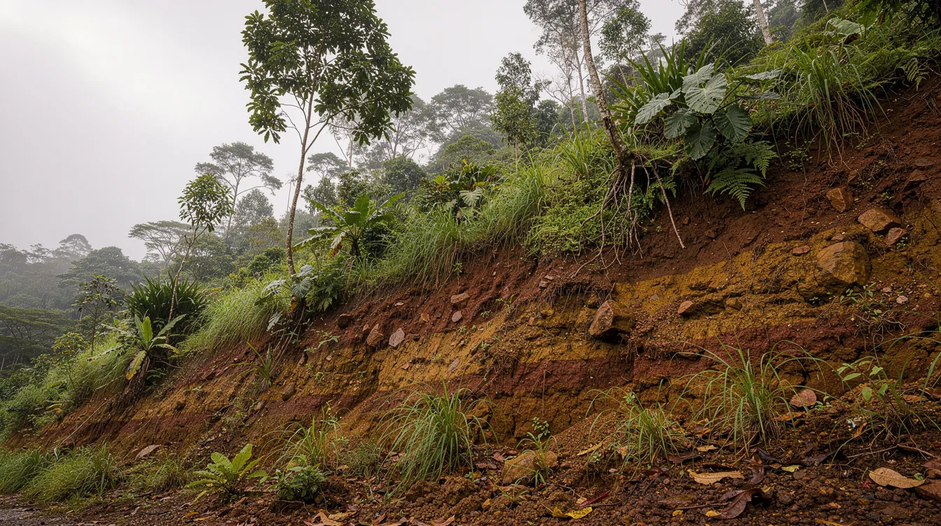
Slope stabilisation in civil engineering encompasses every intervention-design, construction, and maintenance-that ensures a soil mass or rock slope remains stable under environmental loads, construction conditions, and long-term service. In Singapore and across ASEAN, slopes cut into deeply weathered rock, residual soils, and reclaimed fill face particular challenges: intense tropical rainfall, variable groundwater levels, and proximity to dense urban infrastructure. A robust, code-based design framework is therefore essential.
Eurocode 7 establishes design principles for geotechnical structures, and its Singapore adoption-SS EN 1997-provides that framework. Unlike traditional methods that rely on a single safety factor, Eurocode-based design uses limit state principles and partial factors to separately address uncertainties in loads, material properties, and resistances. This distinction has practical consequences for how engineers plan investigations, select soil parameters, and verify slope stability.
The scope of this article covers soil and rock slopes, cuttings, embankments, reinforced soil systems, and retaining structures supporting slopes. It does not address rockfall mesh design or tunnelling-specific ground support.
Role of Eurocode 7 and SS EN in slope design
Eurocode 7 comprises EN 1997-1 for general geotechnical design rules and EN 1997-2 for ground investigation and testing. Singapore has adopted both as SS EN 1997, with a National Annex specifying local partial factors, permitted Design Approaches, and supplementary requirements for ground investigation. Eurocode 7 emphasizes the importance of a reliable ground investigation as the foundation for all subsequent design decisions.
Local documents interface directly with SS EN 1997. The BCA GeoSS Guide on Ground Investigation and Geotechnical Characteristic Values to EC7 mandates accreditation for investigation firms, defines geotechnical categories, and provides procedures for deriving characteristic values. LTA’s Design Criteria for Transport Infrastructure (E/GD/09/106/A3) sets geometry limits and verification requirements for transport slopes. PUB drainage guidelines govern stormwater management integral to slope design.
Under this framework, slopes are verified for ultimate limit state (ULS)-covering global stability, sliding, bearing, and hydraulic failure-and serviceability limit state (SLS)-addressing deformation, long-term movement, and impacts on adjacent infrastructure. The design philosophy must account for both ultimate and serviceability limit states across persistent, transient, accidental, and (where required) seismic design situations. This framework dictates the step-by-step process described in the sections that follow.
Key limit states and design approaches for slopes
Ultimate limit states relevant to slopes include global slip failure along a deep or shallow slip surface, local face failure, sliding or overturning of retaining structures, bearing capacity failure beneath wall foundations, and hydraulic failure such as uplift, piping, or internal erosion where drainage structures interact with the slope. Analyzing the kinematic feasibility of different failure modes is essential for a thorough stability assessment.
Serviceability limit states govern acceptable long-term displacements, crack widths in slope facings, angular distortion near structures, and movement impacts on adjacent utilities. Serviceability Limit States (SLS) checks should ensure movements do not impair nearby infrastructure-a critical concern in Singapore’s dense urban environment.
Design Approach 1 (DA1) requires two load combinations to ensure slope safety: Combination 1 (DA1C1) factors up actions while using unfactored soil strength, and Combination 2 (DA1C2) applies more conservative partial factors to material properties. Singapore’s National Annex prescribes DA1C1 and DA1C2 for global slope stability analysis. DA2 and DA3 exist in other jurisdictions but require specific justification for use in Singapore. Choosing the correct design approach early controls how actions, resistances, and soil parameters are factored in all subsequent calculations.
From global factor of safety to partial factors
The classical global factor of safety approach assesses slope stability as a single ratio of resisting forces to driving forces. The Factor of Safety standard for permanent slopes is 1.5, and a Factor of Safety (FOS) below 1.5 indicates potential slope failure. While straightforward, this method does not distinguish between load uncertainties, soil strength variability, and resistance model accuracy.
Eurocode 7 uses limit state design principles for safety verification, applying separate partial factors to actions and material properties. In practice, many engineers in Singapore interpret a Eurocode-compliant design by re-casting partial-factor checks into an equivalent FoS for communication with contractors and authorities-but the underlying verification must satisfy the partial factor framework of SS EN 1997 with the Singapore National Annex. The following sections show how to move from soil test data to characteristic and design values that underpin these checks.
Core components of a Eurocode-compliant slope stabilisation design
Every component of the step-by-step process rests on accurate definition of the project’s physical and geotechnical inputs: slope geometry, ground conditions, groundwater regime, loads, and performance criteria. If these core components are wrong or incomplete, no amount of sophisticated numerical analysis will rescue the design.
Slope geometry, loading and project context
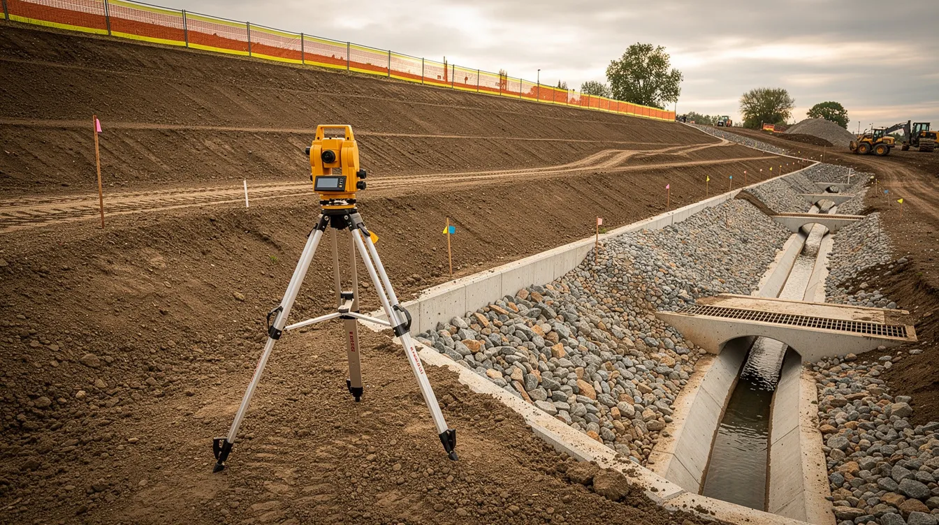
Typical slope geometries in Singapore infrastructure range from highway cuttings 6–15 m in slope height to hillside developments with slopes reaching 25–40 m. LTA criteria limit permanent unreinforced slopes to a maximum gradient of 2H:1V (approximately 26.6°) unless otherwise accepted, and require benches at least 1.5 m wide for any slope over 5 m high. Topographic surveys provide the baseline for defining crest, toe, berms, and any stepped profiles.
Loads to define include self-weight of the soil mass and any overlying structures, traffic surcharge in accordance with SS EN 1991, construction equipment loads, and seismic actions where required by the project brief or BC3 guidelines. The importance of project context cannot be overstated: brownfield sites adjacent to HDB blocks, underground MRT tunnels, or critical water mains demand interaction analyses that greenfield hillside cuts may not.
Ground conditions, groundwater and climatic factors
Singapore’s local geology presents three dominant formations affecting slopes. Bukit Timah Granite residual soils-deeply weathered grades IV to VI-exhibit high variability in shear strength and permeability. Jurong Formation residual soils overlay sedimentary rock with complex layering and weak shale seams. Kallang Formation alluvium and reclaimed fill in coastal areas are characterised by low soil strength and high compressibility. Soil cohesion decreases with depth in residual soils, affecting stability calculations significantly.
Heavy rainfall increases pore-water pressure, reducing slope stability-a phenomenon well documented during Singapore’s Northeast Monsoon, when daily rainfall events exceeding 200 mm have triggered numerous slope failures. Groundwater is a critical driver of slope instability, and under SS EN 1997, design groundwater levels must reflect seasonal and extreme rainfall conditions, not a single borehole reading on one date. Rainfall infiltration and transient seepage cause pore pressure rise that critically reduces the factor of safety, particularly in partially unsaturated slopes with vegetative cover.
Selection of slope stabilisation systems
A concise overview of stabilisation options commonly deployed on Singapore infrastructure includes soil nailing, ground anchors, bored pile walls, contiguous or secant pile walls, reinforced soil walls with geogrids, gabions, rock bolts, and bio-engineered solutions. Soil nails and ground anchors are common stabilization measures used in slope design, while composite anchors can reach tensile strengths up to 5000 kN for heavy-duty applications. GeoBarrier Systems stabilize slopes using reinforced soil walls and capillary barriers, combining mechanical reinforcement with drainage.
Eurocode 7 and SS EN do not prescribe a specific stabilisation system. Engineers must select and design systems that achieve the required limit state performance while satisfying authority criteria for constructability, aesthetics, and maintenance. The step-by-step process below shows where such choices are evaluated and compared.
Step-by-step civil engineering design process for slope stabilisation under SS EN Eurocodes
This section forms the core of the article: a practical, ordered workflow that AEC Technical Advisory typically follows for slopes on infrastructure and building projects in Singapore. While steps are presented linearly, real projects iterate as the project progresses and new information emerges from investigation, analysis, or construction.
Step 1 – Define design brief, constraints and performance criteria
A clear design brief establishes the project type (e.g. 10 m high expressway cutting, hillside platform for an industrial facility), design life (typically 50–100 years for permanent slopes), and operational requirements such as maintenance access, green cover, noise barriers, or aesthetic constraints from NParks.
Constraints to capture include land boundaries and easements, existing and planned utilities, adjacent structures, road alignment, vertical clearance, drainage outfalls, and available construction corridor width. For slopes near existing buildings, acceptable limits for settlement and lateral movement must be defined early.
Target performance criteria include required factors of safety (FoS ≥ 1.5 for permanent slopes, ≥ 1.2–1.3 for temporary slopes per local practice), maximum allowable wall movements, and limits on settlement or tilt affecting nearby buildings. These criteria must be compatible with SS EN 1990/1991 reliability levels and local authority guidelines. Slope stabilisation design requires geotechnical investigation and advanced modelling, and the brief must define the scope for both.
Step 2 – Plan and execute ground investigation to EN 1997-2
The design begins with a desk study reviewing historical plans, geological maps, borehole archives, and BCA/NParks records before any drilling. Eurocode 7 emphasizes the importance of ground investigation in design, and the standard emphasizes the importance of a reliable ground investigation as the basis for all geotechnical design decisions.
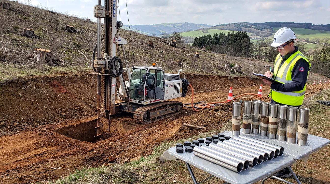
For a typical highway cutting, borehole spacing should cover the alignment with depths extending 1.5–2 times the slope height below anticipated slip surfaces. Ground investigations include boreholes and laboratory testing: Standard Penetration Tests (SPT) or Cone Penetration Tests (CPT) for in situ testing, rotary core drilling for weathered rock, triaxial and direct shear tests for shear strength, oedometer tests for compressibility, grain size analysis for classification, and permeability tests where seepage is critical. Ground investigations must identify soil parameters influencing failure mechanisms.
Groundwater monitoring via standpipes or vibrating wire piezometers should span several months to capture monsoon responses. Pore water pressure is a primary concern in hydrogeological assessments for slopes, and geotechnical investigations help identify groundwater conditions affecting stability.
Slope categories are defined as Geotechnical Category 2 or 3 based on risk. It categorizes projects into three geotechnical categories based on complexity, with slopes near critical infrastructure typically falling into Category 3, requiring the most comprehensive investigation and third-party checking.
Step 3 – Develop a geotechnical ground model
AEC Technical Advisory synthesises borehole logs, laboratory testing data, and geological mapping into a 2D or 3D ground model describing soil layers, rock units, interfaces, weathering grades, and the groundwater regime. This ground model is the single most important design input-it underpins both simple limit equilibrium methods and advanced finite element analyses.
The model must identify likely slip surfaces: colluvium-over-bedrock interfaces, highly weathered rock layers, soft clay seams, and relic shear zones. For Jurong Formation slopes, weak shale laminations can control the critical failure mechanism. Representing uncertainty is essential: zones of variable thickness, interpolated soil layers between boreholes, and data-poor regions should be flagged for caution or further investigation.
Groundwater levels under both dry-season and extreme rainfall conditions must be mapped. For partially unsaturated slopes, matric suction profiles and their loss during rainfall infiltration should be incorporated where soil conditions warrant it.
Step 4 – Select characteristic and design soil parameters
From scattered lab and in situ testing results (cohesion c′, friction angle φ′, unit weight γ, undrained shear strength c_u, permeability k), engineers derive characteristic values according to EN 1997-1 principles-cautious estimates reflecting the relevant ground volume and the governing failure mechanism. Geotechnical investigations assess soil properties for slope stability, and the lowest test result is not always adopted; engineers must account for scatter, trends with depth, sample disturbance, and scale effects.
Design values are then obtained by applying partial factors per the Singapore National Annex. For the STR/GEO limit state under DA1C1 (Set M1), γ_M for φ′ = 1.0 and for c_u = 1.0. Under DA1C2 (Set M2), γ_M for φ′ = 1.25 and for c_u = 1.4-meaning DA1C2 can result in design shear strength 25–40 % lower than the characteristic value. Design value calculations must comply with applicable National Annex specifications. Partial factors are applied to actions and material properties in Eurocode 7, and this step is where those factors directly shape the conservatism of the design.
Parameter selection should be documented transparently in a Geotechnical Interpretative Report, as expected by BCA and other agencies.
Step 5 – Define design situations and loading combinations
Typical design situations include: (a) long-term drained condition after construction (persistent), (b) short-term undrained condition during excavation (transient), (c) extreme rainfall raising groundwater (transient or accidental), and (d) seismic loading if required by the project brief.
Each design situation translates into different load cases with varied groundwater levels, traffic surcharge, building loads, and construction surcharges. For example, a persistent design situation uses the long-term phreatic surface, while a transient situation models the pore pressure rise from a 50-year or 100-year return-period storm. Extreme rainfall events recorded during Singapore’s Northeast Monsoon-with daily totals exceeding 200 mm and antecedent 5-day accumulations above 150–200 mm-provide the basis for transient groundwater profiles.
These design situations are checked under the relevant Design Approach: DA1C1 for load-dominated scenarios and DA1C2 for material-dominated scenarios, in accordance with SS EN 1997. Authorities in Singapore expect explicit demonstration that rainfall-induced transient conditions have been considered for cut slopes.
Step 6 – Perform preliminary global stability analyses
Initial stability analysis is carried out on the existing or proposed slope geometry using limit equilibrium methods-Bishop, Morgenstern–Price, or Spencer-implemented in commercially available software. Slope stability analysis includes Limit Equilibrium Methods and Numerical Modeling, and this preliminary step uses the former to rapidly identify critical conditions.
Inputs include slope geometry from the ground model, soil layers with characteristic or design parameters (depending on the design approach being checked), groundwater profiles for each design situation, and surcharges. The engineer identifies critical slip surfaces-shallow versus deep, toe versus crest failures-and records baseline factors of safety or utilisation ratios for each combination.
These baseline results guide what kind of slope stabilization measures are required and where structural elements should be focused. If the analysis shows adequate stability under all design situations, stabilisation may not be needed; more commonly, the results quantify the shortfall that the stabilisation system must address.
Step 7 – Develop and compare stabilisation concepts
Prepare 2–3 feasible stabilisation concepts, for example: (1) a soil-nailed slope with shotcrete or green facing, (2) a reinforced soil wall with geogrids, or (3) a bored pile or soldier pile retaining wall with ground anchors. Soil nails are commonly used for slope stabilization in tropical climates, and erosion control measures and drainage are important for every option.
Each option is analysed under the critical design situations, verifying whether code-based limit states are satisfied. Comparison considers factor of safety achieved, deformation control, constructability in constrained corridors, environmental impact, and whole-life cost. Vegetation covers can increase slope Factor of Safety by 20 kPa of apparent cohesion, making green-faced solutions attractive where slope geometry and soil conditions allow. Capillary Barrier Systems can maintain negative pore-water pressures during rainfall, offering an additional line of defence.
AEC Technical Advisory advises developers and contractors on which option best balances safety, cost, programme, and authority expectations-drawing on experience with both conventional retaining structures and sustainable green-faced solutions.
Step 8 – Detailed design and numerical modelling
When complex stratigraphy, high slopes, adjacent MRT tunnels, or interaction with piled foundations warrant it, the design moves to numerical modelling using finite element or finite difference methods with the strength reduction technique. PLAXIS and similar tools model construction stages: excavation in lifts, installation of soil nails or anchors, casting of facing, and changing groundwater boundary conditions with drainage installation.
Both ULS (stability against failure) and SLS (predicted displacements, wall deflections, settlements at building locations) are checked against project acceptance criteria. Sensitivity analysis varying φ′, c′, groundwater level, and nail or anchor capacities identifies critical uncertainties to be managed through monitoring or contingency design. The boundary conditions used in the numerical model must reflect realistic support, loading, and drainage assumptions.
Numerical analysis is particularly valuable for deep excavation adjacent to existing buildings or infrastructure, where soil-structure interaction governs performance.
Step 9 – Detailing, durability and drainage design
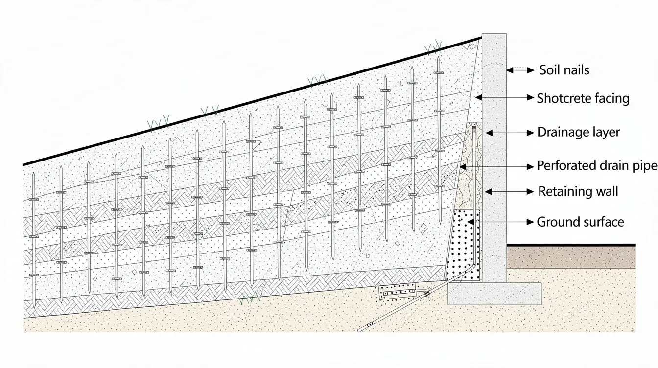
Key detailing tasks include soil nail or anchor spacing and inclination, bond length, corrosion protection class (galvanised, encapsulated, or duplex systems for tropical humidity), facing thickness and reinforcement, connection details between nails and facing, and bearing plates. Rock bolts require similar attention to corrosion protection and grouting quality.
Drainage is a central stabilisation element-often as important as the structural elements themselves. Subsoil drains behind walls, horizontal drains in slopes, crest and toe drains, and lined channels must be designed in coordination with PUB stormwater requirements. Erosion control at the ground surface prevents surface runoff from degrading the slope face and undermining drainage systems. Groundwater management is crucial for effective slope stabilization.
Durability in tropical climates demands concrete cover compliant with SS EN 1992, protective coatings, sacrificial steel thickness, and allowances for aggressive ground or marine environments. Vegetative cover provides long-term erosion control but requires maintenance access and irrigation during establishment.
AEC Technical Advisory typically integrates these details into coordinated civil, structural, landscape, and drainage drawings, often using BIM models to detect clashes and ensure constructability.
Step 10 – Verification, documentation and authority submissions
Design documentation comprises the geotechnical design report, stability calculation packages (including Eurocode partial factor checks for both DA1C1 and DA1C2), drawings, construction sequence notes, and risk assessments. Explicit cross-references to SS EN/Eurocode clauses, National Annex tables, and local practice notes facilitate smoother authority reviews.
Typical authority interfaces in Singapore include BCA for geotechnical design and ERSS submissions, LTA for transport slopes, PUB for drainage, NParks for vegetation, and JTC/URA for industrial or land-use aspects. Professional Engineers (PEs) sign off calculations and drawings, while Accredited Checkers or independent reviewers verify high-risk slopes under local regulations as the PE(Geo) and PE(Civil) framework requires.
Ground conditions should be monitored during construction to manage uncertainties, and the submission should include an instrumentation and monitoring plan as described in Step 11.
Step 11 – Construction monitoring and observational method
Eurocode 7 permits the observational method for situations with significant ground uncertainty-particularly relevant during deep cuts in residual soils or weathered rock. This approach requires that design predictions, trigger levels, and contingency measures are defined before construction begins.
Instrumentation typical for slopes includes inclinometers (subsurface movement), piezometers (pore pressure), settlement markers, load cells on anchors, and surface survey points. Trigger levels are aligned to design predictions: for example, if predicted lateral displacement is 15 mm at a certain construction stage, an alert trigger might be set at 20 mm and a stop-work trigger at 30 mm.
Monitoring data is compared with modelled actual behaviour; deviations beyond defined thresholds trigger pre-agreed contingency measures such as additional nails, supplementary drainage, temporary berms, or changes to excavation sequence. Authorities increasingly expect a monitoring and contingency plan to be part of the ERSS or slope design submission, especially for urban projects. The right consultant integrates BIM modelling and monitoring instrumentation into a unified project delivery.
Common challenges and practical solutions in SS EN slope design
Code knowledge alone is not sufficient for reliable slope design. Poor ground investigation, misinterpretation of partial factors, and construction shortcuts are frequent causes of slope instability in Singapore and the wider ASEAN region. The following subtopics address the most common problems with actionable solutions.
Insufficient or poorly targeted ground investigation
Problem: Too few boreholes, shallow investigation, or missing tests for critical weak layers lead to overly optimistic geotechnical parameters. Slope failures often occur in steep residual soil slopes during rainfall precisely because weak seams or perched water zones were not identified.
Solution: Tie investigation planning to potential failure mechanisms. Extend boreholes below anticipated slip surfaces by at least half the slope height and perform strength tests-including ring shear for residual strength-on suspected shear zones. Document residual uncertainties and, where necessary, adopt the observational method or conservative design values. A comprehensive geotechnical investigation is always cheaper than remediating a failed slope.
Misapplication of Eurocode partial factors and design approaches
Problem: Using default software settings that reflect European National Annexes rather than the Singapore NA-for example, wrong γ_M or γ_Q values, or mixing DA1 and DA2 parameters-can produce non-compliant designs that are rejected at submission or, worse, unsafe in service.
Solution: Require engineers to manually verify partial factors against SS EN 1997 NA tables and cross-check software output using simplified hand calculations. Include a clear summary table in the geotechnical report listing which design approach and partial factors were used for each verification. Peer review by an experienced geotechnical engineer familiar with Singapore practice is essential.
Ignoring rainfall-induced transient conditions
Problem: Designers check only long-term groundwater levels, overlooking short-duration but critical pore pressure rises during heavy storms. Studies of Singapore slope failures during the December 2006 – January 2007 monsoon period showed numerous failures when daily rainfall exceeded approximately 200 mm. Heavy rainfall increases pore-water pressure, reducing slope stability dramatically-especially in low-permeability residual soils where 5-day rainfall accumulation is the critical scenario.
Solution: Model raised groundwater levels or transient seepage corresponding to design storm events (50-year or 100-year return period) and verify both ULS and SLS under these rainfall conditions. Complement structural stabilisation with drainage and surface protection measures. Capillary barriers, surface liners, and vegetation designed for erosion control work synergistically with structural elements.
Underestimating construction and staged excavation effects
Problem: Slopes stable in the final condition can fail during intermediate construction stages due to temporary loss of support, unfavourable groundwater regimes, or unplanned surcharges. These common earthworks failures are preventable.
Solution: Perform staged analyses including temporary slopes, batters, berms, and temporary anchors. Coordinate closely with the contractor’s method statements and require PE review of any changes to construction sequencing, support systems, or dewatering plans.
Poor integration with adjacent structures and utilities
Problem: Slope design done in isolation leads to excessive movement affecting retaining walls, buildings, culverts, or buried services-particularly in Singapore’s constrained urban environment.
Solution: Adopt an integrated civil-structural-geotechnical approach with BIM coordination. Explicitly model the interaction between slopes and shallow foundations, culverts, and pipelines. AEC Technical Advisory’s capability to combine civil, structural, geotechnical, and M&E inputs ensures that slope stabilisation and adjacent infrastructure are designed as a coherent system.
Conclusion and next steps
Robust slope stabilisation design under SS EN Eurocodes follows a disciplined workflow: thorough ground investigation → realistic ground model capturing soil layers, interfaces, and groundwater → careful selection of characteristic values and design parameters → limit state checks using DA1C1 and DA1C2 with Singapore National Annex partial factors → detailed, buildable solutions backed by drainage design and monitoring. Each step builds on the previous one, and shortcuts at any stage introduce risks that compound through the project.
Eurocode 7 and its SS EN adoption provide a consistent safety framework that replaces the ambiguities of a single global factor with transparent, auditable partial factor checks. But engineering judgement and local experience in tropical soil conditions, intense rainfall conditions, and Singapore’s regulatory landscape remain critical. No code replaces the need for competent professionals who understand both the soil mechanics and the practical realities of construction.
Immediate next steps for readers:
-
Audit current or planned slopes against the 11-step process described above to identify gaps in investigation, analysis, or documentation
-
Review whether existing designs correctly apply SS EN partial factors for both DA1C1 and DA1C2 using the Singapore National Annex values
-
Confirm that transient groundwater conditions from extreme rainfall events have been modelled, not just steady-state levels
-
Verify that a monitoring and contingency plan exists for every slope classified as Geotechnical Category 2 or 3
-
Engage a qualified civil/geotechnical consultant to review geotechnical categories, parameter selection, and monitoring needs
AEC Technical Advisory supports projects from initial feasibility and ground investigation planning through Eurocode-compliant geotechnical design and BIM coordination, to authority submissions, construction monitoring, and periodic slope inspections. Consultants should have a proven local authority submission track record, and our team brings that experience across BCA, LTA, PUB, and NParks interfaces.
Related topics readers may wish to explore include deep excavation design to Eurocode 7, reinforced soil walls, foundation design in residual soils, and rainfall–infiltration modelling for tropical slopes.
Additional resources and technical checklist
This section serves as a practical appendix: reference lists, a design checklist, and prompt questions for early project discussions. It is designed to be printed or saved as an internal project tool.
Key codes, standards and guidance for slope stabilisation
-
SS EN 1997-1:2010 (with Singapore National Annex, 2018 amended) – General rules for geotechnical design
-
SS EN 1997-2:2010 (with Singapore National Annex) – Ground investigation and testing
-
SS EN 1990 – Basis of structural design (reliability framework)
-
SS EN 1991 – Actions on structures (surcharge, traffic, wind)
-
BCA GeoSS Guide on Ground Investigation and Geotechnical Characteristic Values to EC7 (2015)
-
BCA Framework on Risk Based Slope Design (2023) – DA1C1/C2 requirements, subsoil drain design, climate change considerations
-
LTA Design Criteria E/GD/09/106/A3 – Slope geometry limits, berming, drainage for transport infrastructure
-
PUB drainage design guidelines – Stormwater management for slopes and channels
-
CIRIA guidance on soil nailing, reinforced soil, and slope stability assessment under rainfall (international reference)
While these documents inform design, project-specific ground models and professional judgement in rock engineering and soil mechanics remain essential.
Eurocode-based slope design checklist for project teams
-
☐ Design brief defined: project type, design life, performance criteria, authority requirements
-
☐ Geotechnical category assigned (Category 2 or 3) and investigation scope scaled accordingly
-
☐ Ground investigation completed to SS EN 1997-2 with adequate depth, spacing, and test types
-
☐ Groundwater monitoring data covers at least one monsoon season
-
☐ Ground model developed with all soil layers, interfaces, weathering profiles, and groundwater regimes
-
☐ Characteristic values derived per EN 1997-1 principles with documented rationale
-
☐ Design approach confirmed (DA1C1 and DA1C2 per Singapore NA) with correct partial factors
-
☐ Design situations defined: persistent, transient (including extreme rainfall), accidental, seismic if applicable
-
☐ ULS global stability verified for all critical slip surfaces under all design situations
-
☐ SLS deformation checks completed against acceptable limits for adjacent structures and utilities
-
☐ Stabilisation system detailed: spacing, inclination, bond length, corrosion protection, facing, drainage
-
☐ Drainage design coordinated with PUB requirements; surface and subsurface systems specified
-
☐ Construction sequencing analysed for temporary stability during all construction stages
-
☐ Monitoring plan with instrument types, trigger levels, and contingency measures included
-
☐ Documentation cross-references SS EN clauses and NA tables; PE and Accredited Checker sign-off obtained
Use this checklist in design reviews, peer reviews, and pre-submission audits before sending documents to BCA, LTA, or other authorities. AEC Technical Advisory can adapt this checklist to specific corporate standards or asset owner requirements.
Early-stage questions to ask your slope design consultant
-
“How will you classify the geotechnical category and what does that mean for investigation and groundwater monitoring scope?”
-
“Which SS EN 1997 Design Approach will you use for global stability, and why?”
-
“How will you derive characteristic values from lab and in situ testing results-what statistical or judgemental method?”
-
“How will you account for extreme rainfall and transient groundwater effects in your stability analysis?”
-
“What software and verification methods will you apply for limit equilibrium and numerical modelling?”
-
“How will you coordinate slope design with drainage, utilities, and adjacent structures in BIM?”
-
“What is your plan for instrumentation, trigger levels, and responding to unexpected ground behaviour during construction?”
-
“How do you address durability and corrosion protection for soil nailing and ground anchors in tropical conditions?”
-
“What is your experience with BCA and LTA submissions for similar slope projects?”
-
“How will you handle construction sequencing to ensure stability at every stage, not just the final condition?”
-
“What sensitivity analysis will you perform on critical soil parameters and groundwater assumptions?”
Use the responses to gauge the consultant’s familiarity with SS EN Eurocodes, local authority processes, and tropical ground conditions.
How AEC Technical Advisory typically delivers SS EN-compliant slope designs
-
Integrated design: Civil, structural, and geotechnical engineering delivered within one team, eliminating coordination gaps between disciplines
-
Early involvement: Engaged from feasibility and GI planning to ensure investigation scope matches design ambition and authority expectations
-
Eurocode-consistent tools: Internal checklists, verified software configurations aligned to Singapore NA partial factors, and peer-review protocols
-
Authority submissions: Proven track record managing BCA, LTA, PUB, NParks, and SCDF submissions for slope and retaining structure projects across Singapore
-
Full range of systems: Experience with conventional retaining systems (soil nails, pile walls, reinforced soil) and sustainable green-faced solutions meeting local landscape expectations
-
Beyond design: Periodic slope and retaining wall inspections, PE endorsements, and advisory work when existing slopes show distress after heavy rainfall events
-
BIM integration: Coordinated civil, structural, landscape, and drainage models ensuring constructability and clash-free detailing
We invite readers to share preliminary layouts, slope profiles, or GI data for an initial discussion on appropriate SS EN Eurocode-based design approaches. Contact AEC Technical Advisory to explore how we can support your next slope stabilisation project.